A grounding system (also called an earthing system) is an essential part of electrical installations, ensuring safety, preventing electric shocks, protecting equipment, and maintaining the stability of power systems. Below is a detailed breakdown of the components that constitute a grounding system and their respective functions:
1. Grounding Electrode (Earth Electrode)
The grounding electrode is the core component of the grounding system, which establishes a physical connection with the earth. It allows electrical currents (such as fault currents or lightning surges) to dissipate safely into the ground.
Types:
- Natural Grounding Electrode: Utilizes existing underground metallic structures, such as water pipes, building foundation rebar (reinforcing steel), or buried metallic tanks.
- Artificial Grounding Electrode: Includes metal rods, plates, pipes, or strips specially installed underground to serve as the grounding point.
Material:
- Common materials include copper, galvanized steel, and aluminum, selected for their conductivity, durability, and resistance to corrosion.
- These materials must meet specific standards to ensure low electrical resistance and long-term performance.
Design:
- The electrode must have sufficient contact with the soil, requiring proper depth and placement.
- In cases of poor soil conductivity, auxiliary measures like soil treatment (adding salt or chemical compounds) are employed to reduce resistance.
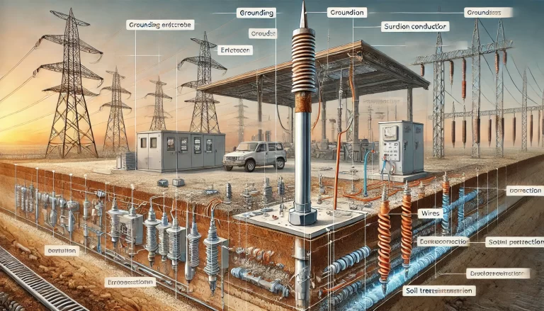
2. Grounding Conductor
The grounding conductor connects the electrical system or equipment to the grounding electrode. It provides a low-resistance path for fault currents to travel safely to the earth.
Material and Construction:
- Conductors are typically made of copper or aluminum, chosen for their high conductivity and resistance to heat during fault conditions.
- Insulated or bare wires are used depending on the installation’s environmental conditions and safety requirements.
Sizing:
- The cross-sectional area of the grounding conductor must be sufficient to handle maximum fault currents without overheating or breaking.
- Compliance with national or regional standards (e.g., IEEE, NEC, or IEC) is critical.
3. Grounding Grid (Earth Mat)
A grounding grid is a network of interconnected grounding electrodes and conductors, designed to extend the effective grounding area and ensure uniform ground potential.
Applications:
- Large-scale installations such as substations, power plants, and industrial facilities.
- Reduces step and touch potential to enhance personnel safety.
Construction:
- Made by interconnecting multiple grounding rods, plates, or wires into a mesh structure.
- Buried horizontally in the soil at a specific depth to increase contact with the earth.
4. Protective Devices
Protective devices monitor and safeguard the grounding system, ensuring that faults are detected and corrected before causing harm.
- Key Devices:
- Grounding Resistance Tester: Measures the resistance between the grounding electrode and the earth to ensure compliance with safety standards.
- Residual Current Device (RCD): Detects leakage currents and disconnects the power supply to prevent electric shock.
- Surge Protective Devices (SPD): Protect equipment from voltage spikes caused by lightning or switching operations.
5. Equipment Grounding
Electrical equipment and structures that could become energized in fault conditions must be grounded to prevent accidental electric shock or damage.
- Examples:
- Metal enclosures of electrical devices (transformers, motors, panels).
- Shielding layers of cables to minimize electromagnetic interference.
- Steel structures such as towers and poles.
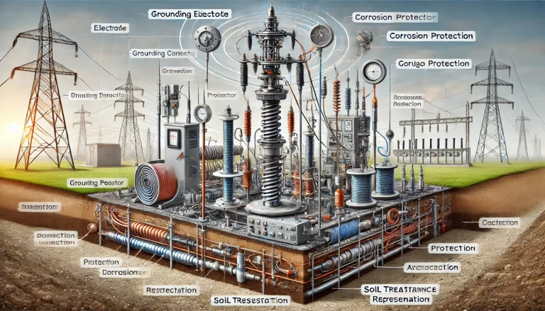
6. Auxiliary Systems
Auxiliary systems are supplemental components designed to enhance the grounding system’s performance and longevity.
Corrosion Protection:
- Grounding materials are often exposed to soil conditions that can cause corrosion. Protective coatings or the use of corrosion-resistant materials (e.g., copper-clad steel) is common.
Voltage Equalization:
- Equipotential bonding systems reduce potential differences between different parts of the installation, preventing dangerous step voltages.
Soil Treatment:
- In areas with high soil resistivity, substances like bentonite clay or salt compounds may be added to the soil around the electrode to improve conductivity.
7. Grounding System Integration
Grounding systems are integrated with other safety systems to ensure comprehensive protection. For instance:
- Lightning Protection Systems: Directly connect to the grounding system to discharge lightning currents safely into the earth.
- Neutral Grounding: In power systems, the neutral conductor is often grounded to stabilize voltage levels during unbalanced conditions.
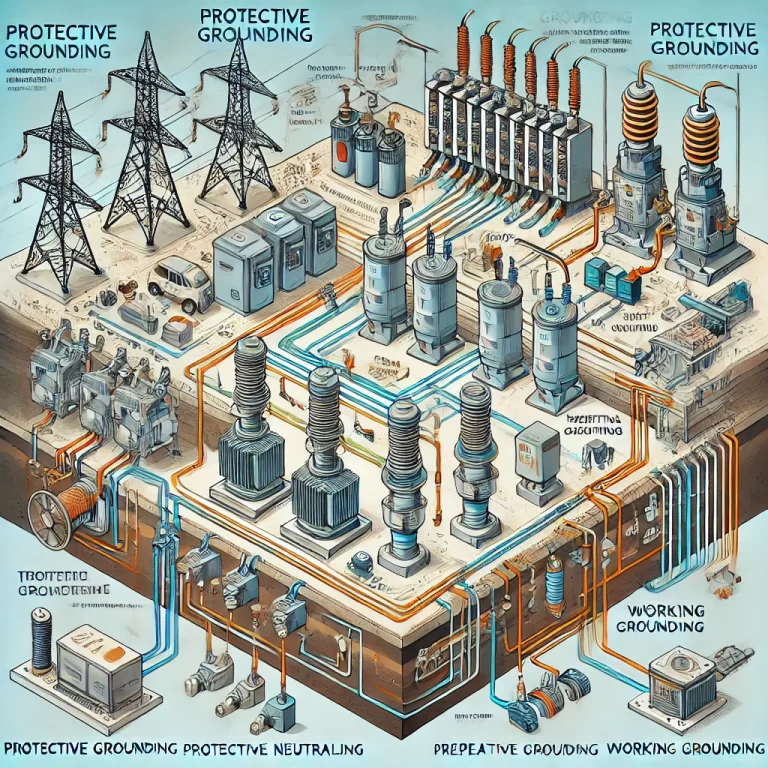
Classifications of Grounding Systems
- Protective Grounding: Ensures the safety of people and equipment by grounding metal parts that might become energized.
- Functional Grounding: Facilitates proper operation of electrical systems, such as grounding for shielding against electromagnetic interference (EMI).
- Lightning Grounding: Protects structures from lightning strikes by safely channeling the discharge to the earth.
- Signal Grounding: Ensures stable references for sensitive electronic devices, such as communication and instrumentation systems.
Key Design Considerations
Ground Resistance:
- Low resistance is critical for effective grounding. Target values often depend on system requirements but are typically below 5 ohms for safety purposes.
Soil Resistivity:
- Grounding system performance depends on soil resistivity, which varies with moisture, temperature, and composition. Proper site assessment and soil treatment may be necessary.
Connection Quality:
- All connections in the grounding system must be secure, low-resistance, and corrosion-resistant to ensure long-term reliability.

Conclusion
The grounding system is a foundational safety feature for any electrical installation. Its proper design, implementation, and maintenance are essential for protecting human lives, safeguarding equipment, and ensuring the reliable operation of electrical systems. Standards such as IEEE, NEC, and IEC provide detailed guidelines for designing and maintaining effective grounding systems.