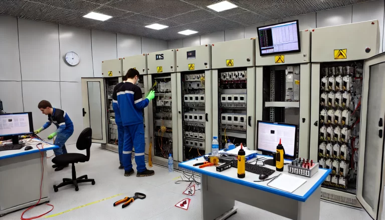
In the field of instrument fault diagnosis, understanding and correctly using technical terms is essential for effective communication and problem-solving. This article provides detailed definitions, examples, and categorization of common terminologies to aid professionals and learners in the industry.
1. Fundamental Terms
1.1 Fault (Fault):
A fault is an unexpected condition that prevents a functional unit from performing its specified functions.
Example: A temperature sensor’s inability to produce accurate readings due to internal wiring damage.
1.2 Failure (Failure):
The termination of a functional unit’s ability to perform its intended functions.
Example: A pressure gauge permanently ceasing to display pressure due to a broken mechanism.
2. Measurement and Error Terms
2.1 Zero Drift:
Also known as zero-point drift, this refers to a deviation at the lower range limit. When the lower limit is not zero, it is also called initial point drift.
Example: A scale showing 0.5 kg when there is no load.
2.2 Point Drift:
The change in output corresponding to a constant input over a specified time under reference conditions.
Example: A voltage sensor gradually shifting its readings while monitoring a stable power source.
2.3 Drift:
A gradual, undesired change in the input-output relationship of an instrument over time, not caused by external influences.
Example: A pH sensor showing higher values over time without any actual change in the liquid’s pH.
2.4 Repeatability:
The degree to which an instrument provides consistent output values for the same input value under the same operating conditions when measured consecutively in the same direction.
Example: A flow meter giving identical readings for the same water flow in repeated tests.
2.5 Repeatability Error:
The algebraic difference between the extreme values of outputs measured for the same input under identical conditions over a short time.
Example: A gauge providing values ranging from 5.1 to 5.3 bar when the actual pressure is 5.2 bar.
2.6 Span Error:
The difference between the actual and specified output ranges.
Example: A thermometer designed for a range of 0°C to 100°C, showing an actual range of -2°C to 98°C.
2.7 Zero Error:
The difference between the actual output value and the specified minimum output range value when the input is at the lower range limit.
Example: A pressure sensor outputting 0.2 mA instead of 0 mA at zero pressure.
2.8 Zero Shift:
A change in the output value at the lower range limit caused by certain influences.
Example: An accelerometer showing a baseline offset due to temperature fluctuations.
2.9 Error of Indication:
The difference between the instrument’s indication and the (agreed) true value of the measured variable.
Example: A thermometer showing 25°C when the true temperature is 24.8°C.

3. Sampling and Timing Terms
3.1 Sampling:
The process of taking values of a measured variable at regular time intervals.
Example: A digital multimeter recording voltage every second.
3.2 Sampling Rate:
The frequency at which the measurements are sampled, expressed as the number of samples per unit time.
Example: A data acquisition system recording at 1000 Hz.
3.3 Scan Rate:
The rate of accessing a series of analog input channels, expressed in channels per second.
Example: A data logger scanning 16 channels at 500 scans per second.
3.4 Dead Time:
Also called delay time, it is the period between the instant an input changes and the output begins to respond.
Example: A flow meter taking 2 seconds to register a change in flow rate.
3.5 Damping:
The dissipation of energy in a system during motion.
Example: A needle on a pressure gauge slowly settling to the correct reading after an abrupt pressure change.
Types of Damping:
Periodic Damping (Underdamping): Exhibits overshoot in a step response.
Example: A gauge needle oscillating before stabilizing.
Aperiodic Damping (Overdamping): Does not exhibit overshoot in a step response.
Example: A gauge needle slowly rising to the correct value without overshoot.
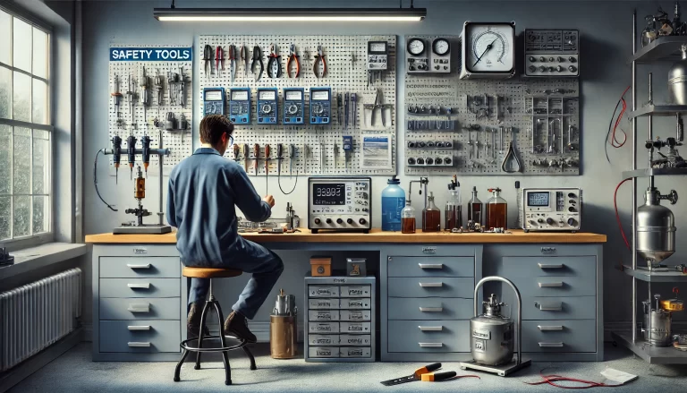
4. Practical Recommendations
Contextual Relevance: Each term should be understood in the context of specific applications or diagnostic scenarios.
Regular Calibration: Ensuring instruments are calibrated periodically reduces errors such as drift and zero shift.
Instrument Documentation: Familiarize yourself with the specifications and limitations of each instrument to interpret diagnostic terms accurately.
By mastering these terminologies and their applications, professionals can effectively diagnose faults, optimize instrument performance, and maintain operational reliability.