
Why More Alarms and Interlocks Do Not Always Mean Safer Operation?
In industrial plants, engineers often assume:
Earlier alarms, more interlocks, and more protection systems always mean higher safety.
However, real process safety design does not work this way.
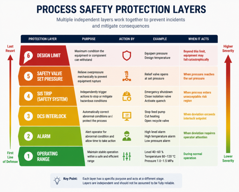
Operating range, alarm limits, DCS interlock values, SIS trip settings, safety valve set pressure, and equipment design limits cannot simply be arranged from low to high.
The key questions are:
- What is the purpose of each protection layer?
- How much time is available from detection to action completion?
- Where will the process parameter finally stabilize after the protection action?
Without answering these questions, safety settings are only numbers in a document — not an effective protection strategy.
1. Normal Operating Range
The operating range defines where the process is expected to run continuously and reliably.
It is not about the maximum pressure or temperature the equipment can withstand.
Instead, it focuses on:
- Stable process control;
- Normal equipment performance;
- Remaining adjustment margin;
- Ability to absorb process fluctuations.
For example, a separator vessel may normally operate at:
Liquid level: 40%–60%
This does not mean 61% immediately creates danger.
It means that within this range:
- Gas-liquid separation remains effective;
- Pump suction conditions remain stable;
- Control valves still have adjustment capacity;
- Upstream and downstream fluctuations can be absorbed.
Two practical indicators show whether the operating range is reasonable:
1. Is the control valve continuously near fully open or fully closed?
If a valve stays at 100% opening for a long time, the system has already lost control margin even though the process value is still within limits.
2. Does the operator frequently need manual adjustment?
A stable process should not require constant intervention.
The operating range answers:
“Where should the process normally operate?”
The design limit answers:
“What can the equipment physically withstand?”
They are not the same concept.
2. Alarm Setting
An alarm is not the end of a dangerous condition.
It is the starting point for human intervention.
Alarm settings should not only consider the distance from normal operation.
They must consider:
How much response time does the alarm provide?
For example:
A vessel normally operates below 60% level.
- High alarm: 70%
- High-high trip: 80%
If the level rises at:
1% per minute
The operator has around 10 minutes to:
- Check valve positions;
- Start standby equipment;
- Reduce incoming flow.
However, if the level rises at:
8% per minute
The same 10% difference only provides about one minute.
The alarm may appear, but there is almost no time for manual action.
An effective alarm must satisfy three conditions:
- The abnormal condition requires attention;
- The operator knows what action to take;
- Enough time exists before the next protection layer activates.
Therefore:
The value of an alarm is not how far it is from normal operation, but what the operator can still do after receiving it.
3. DCS Interlock
DCS interlocks are designed to handle abnormal operating conditions and protect normal production.
Typical examples include:
- High level → Stop feed pump;
- High temperature → Reduce or cut heating source;
- Low level → Stop pump;
- Low pressure → Open recycle valve;
- Insufficient cooling water → Reduce equipment load.
It is important to distinguish:
DCS Control vs DCS Interlock
DCS control:
A continuous adjustment function.
Example:
Temperature increases → Control valve gradually closes steam flow.
DCS interlock:
A protective action triggered at a predefined limit.
Example:
High-high temperature reached → Shut down heating source.
The main difference:
| Function | Purpose |
|---|---|
| DCS Control | Maintain normal operation |
| DCS Interlock | Correct abnormal conditions automatically |
However, DCS is usually connected with common:
- Controllers;
- Network;
- I/O modules;
- Power supply.
Therefore, DCS interlocks should not automatically be considered independent safety protection.
4. SIS (Safety Instrumented System) Trip
SIS is designed for dangerous scenarios identified through risk assessment.
Its purpose is not production optimization.
Its purpose is:
To reduce risk by stopping hazardous conditions before they develop into major accidents.
Typical SIS actions include:
- Emergency shutdown;
- Closing fuel gas valves;
- Stopping compressors;
- Cutting hazardous feed;
- Isolating high-pressure sources;
- Activating emergency cooling systems.
The difference between DCS and SIS is not simply that SIS has a higher trip value.
The fundamental difference is:
DCS:
Responsible for process control and operational protection.
SIS:
Responsible for independent risk reduction.
A common mistake is using the same transmitter for:
- Process control;
- Alarm;
- DCS trip;
- SIS trip.
Although this appears to create multiple protection layers, all functions still depend on the same measurement point.
If the transmitter fails due to:
- Blockage;
- Signal freezing;
- Sensor failure;
Multiple protection functions may fail simultaneously.

5. SIS Trip Setting and Process Overshoot
SIS settings must consider what happens after the action starts.
For example:
A reactor temperature limit:
- Maximum allowable temperature: 200°C
- Shutdown valve closing time: 4 seconds
- Additional temperature rise after shutdown: 8°C
- Measurement uncertainty: 2°C
If SIS trip is set at 198°C:
The actual temperature may still exceed the allowable limit.
Therefore, SIS settings must consider:
- Measurement error;
- Signal processing delay;
- Logic solver response time;
- Valve actuator travel time;
- Continued temperature or pressure increase after action.
The correct question is not:
“When does SIS activate?”
The correct question is:
“After SIS activation, where will the process finally stop?”
6. Safety Valve Set Pressure
A safety valve works independently from:
- Operators;
- DCS;
- SIS logic.
It opens mechanically when pressure reaches the set pressure.
The safety valve set pressure is:
- Not the equipment failure pressure;
- Not the normal operating pressure.
It is the pressure point where the valve begins to open.
After opening, pressure may continue increasing.
Therefore, engineers must check:
- Allowable overpressure;
- Accumulation pressure;
- Inlet pressure loss;
- Back pressure;
- Required relieving capacity.
SIS and safety valves provide different protection functions.
SIS:
Removes the cause of overpressure.
Examples:
- Stop feed;
- Cut heating;
- Stop compressor.
Safety Valve:
Controls the consequence.
Example:
- Release excess pressure.
A SIS does not replace a safety valve.
A safety valve does not replace SIS protection.

7. Equipment Design Limits
Design pressure and design temperature are used for:
- Material selection;
- Wall thickness calculation;
- Mechanical design;
- Manufacturing inspection.
They are not normal operating targets.
The equipment design limit is also not always equal to the process safety limit.
Examples:
- Vessel shell can withstand pressure, but seals may fail;
- Reactor pressure is acceptable, but catalyst may be damaged;
- Heat exchanger pressure is normal, but differential pressure exceeds tube sheet limits;
- Tank body is safe, but internal components fail.
Therefore, protection settings must consider:
- Internal components;
- Seals;
- Accessories;
- Catalysts;
- Pipelines;
- Downstream equipment.
8. Relationship Between Six Protection Values
The relationship can be summarized as follows:
Operating Range
Where the process normally operates.
Alarm Value
When operators need to take action.
DCS Interlock
When automatic corrective action is required.
SIS Trip
When independent safety action is required.
Safety Valve Set Pressure
When mechanical pressure relief starts.
Design Limit
Where equipment reaches its designed boundary.
These values are not simply arranged by numerical order.
They represent different protection layers.
9. High and Low Parameter Protection Logic
For high pressure, high temperature, and high level:
Typical sequence:
Normal operating limit
↓
High alarm
↓
DCS high-high trip
↓
SIS trip
↓
Final process peak
↓
Allowable equipment limit
For low pressure, low flow, and low level:
The sequence is reversed.
The key point is:
Always evaluate the final process condition after the protection action, not only the trip value itself.

10. Fixed Percentage Spacing Is Not a Reliable Method
A common mistake is:
- Alarm = 5% above normal;
- DCS trip = another 5%;
- SIS trip = another 5%.
This may look neat in a spreadsheet.
But it does not prove safety.
The correct evaluation must include:
- Process response speed;
- Instrument accuracy;
- Signal filtering;
- Scan time;
- Logic response time;
- Valve closing time;
- Material inventory;
- Reaction heat.
Example:
SIS pressure trip:
1.70 MPa
Safety valve set pressure:
1.76 MPa
Difference:
0.06 MPa
Looks acceptable.
However:
Valve closing time: 6 seconds
Pressure rise rate: 0.015 MPa/s
During valve movement:
Pressure increases:
0.015 × 6 = 0.09 MPa
The pressure may still exceed the safety valve setting.
Therefore:
Protection margins must be calculated based on time and process dynamics, not only pressure difference.
Engineering Review Checklist
When reviewing alarm, DCS, SIS, and safety valve settings, ask four questions:
1. What abnormal scenario does this protection address?
2. Which system or person performs the action?
3. How long does it take from detection to completed action?
4. Where will the process parameter finally stabilize?
These questions are much more meaningful than simply asking:
“Should the high alarm be 90% or 95%?”
A protection system is effective only when the complete chain — detection, decision, action, and final process response — is properly designed.