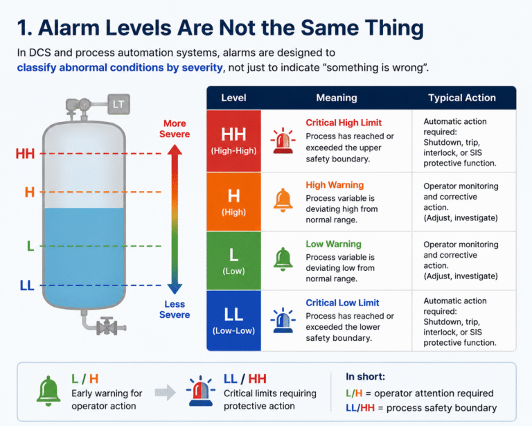
How to Set L, H, LL, HH Alarms in DCS Systems? / Instrumentation In industrial control rooms, alarms are often more critical than operators realize.What causes confusion is not the alarm itself — but not knowing how severe it is.L, H, LL, HH… these four simple letters define completely different levels of process risk. 1. Alarm Levels Are Not the Same ThingIn DCS and process automation systems, alarms are designed to classify abnormal conditions by severity, not just to indicate “something is wrong”.L (Low Alarm) and H (High Alarm)→ Early warning for process deviationLL (Low-Low) and HH (High-High)→ Critical limits requiring protective actionIn short:L/H = operator attention requiredLL/HH = process safety boundary 2. L and H: Early Operational WarningsL and H alarms are used to indicate that a process variable is drifting away from its normal operating range.Examples include:Level too low or too highPressure or temperature deviationFlow instabilityAt this stage, operators are expected to:Adjust control valvesChange pump speedModify process setpointsInvestigate upstream/downstream disturbances👉 The goal is to bring the process back to normal before it becomes critical. 3. LL and HH: Critical Process LimitsLL and HH alarms indicate that the process has reached or exceeded safe operating boundaries.At this level, the situation may lead to:Equipment damage (pump dry-run, seal failure)Overpressure or overflowSafety risks or environmental releaseTypical system responses may include:Pump tripInlet/outlet valve closureEquipment shutdownEmergency interlock activation (SIS)👉 LL/HH are not “warnings” — they are protective thresholds. 4. Alarm ≠ Protection (Important Design Principle)A common mistake in projects is treating L/H/LL/HH as a simple “extra alarm layer” on the same transmitter.In reality:DCS alarms = operator guidanceInterlocks = automatic actionSIS (Safety Instrumented System) = independent protection layerIf LL or HH is used for safety protection, it must be validated through:HAZOP / LOPA studiesIndependent logic or separate measurement where requiredDefined shutdown philosophy👉 Alarm systems inform. Protection systems act. 5. Alarm Design Must Match Process Response TimeAlarm setpoints should not be arbitrary.If set too close:Operators cannot react in timeIf set too wide:Frequent nuisance alarms lead to alarm fatigueIf set too loose:Protection may come too late, resulting in equipment damageProper alarm design must consider:Process dynamics and inertiaInstrument response delayControl valve response timeOperator reaction timeEquipment allowable limits👉 Alarm thresholds represent available reaction time windows, not just numbers. 6. Example: Tank Level ApplicationA typical storage tank system:L Alarm:Low level warning → operator should refill or reduce dischargeLL Alarm:Critical low level → pump trip to prevent dry running and mechanical damageH Alarm:High level warning → reduce inflow or increase dischargeHH Alarm:Overfill risk → inlet shutdown or interlock activation to prevent overflow Final ConclusionL, H, LL, and HH alarms are not just labels in a control system.They represent a structured process safety hierarchy:L/H → early detection and operator correctionLL/HH → defined safety limits and protective actionA well-designed alarm system is not about quantity — it is about:Clear meaningDefined response actionsProper timingClear responsibilityGood alarms do not just sound frequently — they sound correctly, at the right time, and trigger the right action. Share This Story, Choose Your Platform! Contact Us Please prove you are human by selecting the truck. Request a Quote