1. Grounding Devices in DCS Systems
- Operator consoles, printers, and server cabinets: Equipped with protective ground screws.
- Relay cabinets, U cabinets, and distribution cabinets: Equipped with protective ground screws.
- DCS I/O cabinets: Equipped with shielded grounding busbars and protective ground screws. The system ground (+24V ground) is floating.
- Instrument cabinets and operator panels: Equipped with shielded grounding busbars and protective ground screws.
- Safety barrier cabinets: Equipped with shielded grounding busbars and intrinsic safety grounding busbars, with protective ground screws.
2. Signal Shielding and Grounding
- According to relevant technical regulations, the shielding layer of signal cables for computers or DCS systems must not float and must be grounded. Grounding methods should follow the rules below:
- If the signal source is floating, the shield should be grounded at the computer side.
- If the signal source is grounded, the shield should be grounded at the signal source side.
- If the amplifier is floating, one end of the shield should be connected to the shield cover, and the other end should be grounded to a common mode ground (signal ground if the source is grounded, field ground if the source is floating).
- When the shielded cable passes through a junction box, the shields of the two ends should be connected inside the box.
- The selection and installation of DCS system signal cables should strictly comply with the relevant regulations. The shielding layer of cables should be grounded according to the above requirements. To improve the DCS system’s resistance to interference, it is suitable to use flame-retardant twisted-pair copper shielded cables for digital I/O signals.
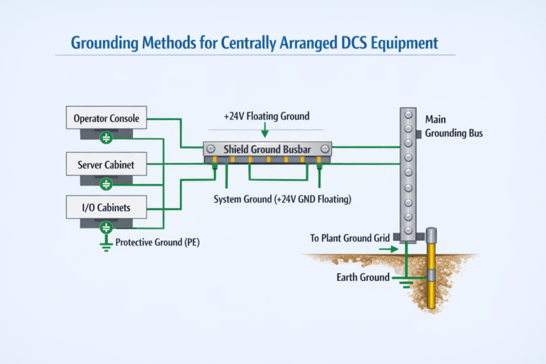
3. Grounding Methods for Centrally Arranged DCS Equipment
4. Grounding Methods for Distributed DCS Equipment
- Distributed DCS system equipment is typically connected through network (communication) cables, for example: the field control stations are distributed across the site, while the operator stations are located in different control rooms. The distance between stations can be up to 500 meters, and they are connected via multi-mode fiber optics, Cat 5 twisted-pair cables, or DP shielded twisted-pair cables.
- For sites using fiber optic connections, the grounding method is the same as for centralized DCS equipment.
- For sites using Cat 5 twisted-pair or DP shielded twisted-pair cables:
- Grounding lines from the control room are first connected to a common connection panel, which then connects to the main ground via a grounding bus. The entire grounding network forms a star-shaped structure.
- The twisted-pair cables are connected to DCS equipment such as switches, hubs, or repeaters through network surge protection devices (signal lightning protectors, with a current rating of at least 5KA). Each station has its own ground electrode, and these electrodes are not required to be metal-connected. The grounding method of each station is the same as for centralized DCS equipment.
- The Cat 5 twisted-pair or DP shielded twisted-pair cables must be laid through galvanized steel conduits or metal cable trays, which must be reliably grounded. Surge protection devices help protect equipment when lightning or electrical faults cause large voltage differences between stations.
5. DCS Equipment Grounding Installation
- Grounding electrodes: Grounding electrodes are conductive bodies driven into the ground, where the current from the grounding bus is discharged into the earth. The connection between the grounding electrode and the grounding bus should be copper-welded and corrosion-treated after welding. Grounding networks can connect multiple electrodes, and these must meet DCS system grounding resistance requirements.
- Typical single and multiple grounding electrode installations:

6. Methods for Reducing Soil Resistivity for DCS Systems
- Change the soil structure around the grounding electrode: Mix substances that are not water-soluble but have good water absorption properties (e.g., charcoal, coking coal slag, or slag) into the soil within 2-3 meters of the electrode. This method can reduce the soil resistivity to 1/5 to 1/10 of the original value.
- Use of salt and charcoal: Layer charcoal and salt in a compacted manner (10-15 cm of charcoal and 2-3 cm of salt) around the grounding electrode. This method reduces soil resistivity to 1/3 to 1/5 of the original value, but salt will gradually wash away over time and needs to be replenished every two years.
- Use of long-lasting chemical resistivity reducers: This method can reduce soil resistivity to 40% of the original value.
7. Grounding Materials and Requirements for DCS Systems
- Materials for grounding electrodes and busbars: The specification for grounding electrodes and busbars can be chosen from the provided table. If grounding resistance requirements are not met, copper can be used. If the installation site is highly corrosive, protective measures such as hot-dip galvanization or tin plating should be taken.
- Grounding wire specifications: Grounding wires and cables for DCS systems should use copper-core insulated wires or cables. When the grounding distance is long or the system requires high grounding resistance, larger section wires should be selected.

8. Common Grounding Considerations on Site
- Field control stations: The grounding screw on the cabinet body must be connected to the grounding busbar, ensuring proper isolation and grounding.
- Field control stations (operator stations, engineering stations, network switches, servers, etc.): External shell grounding or direct connection to the electrical grounding network is required.
- I/O modules: The negative end of DC 24V (terminal 40) must be connected to the logic ground bus, which in turn should be connected to the shielded ground and the main grounding bus.
- Testing grounding resistance: Grounding resistance should be tested to ensure it meets the manufacturer’s requirements for the control system.