1. Boiler DCS Displaying Multiple Faulty Parameters, Leading to Shutdown
Fault Diagnosis:
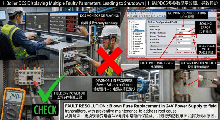
Upon inspecting the DCS display, it was found that the parameters such as steam drum level, feedwater flow, main steam flow, and deaerator water level were all showing as faulty points. Based on experience, it was judged that the issue likely lies with the field transmitters. Upon further inspection, the 24V power supply fuse was found to be blown.
Fault Resolution:
After replacing the fuse, the DCS system returned to normal.
Maintenance Summary:
This case was caused by a blown fuse in the 24V power supply, which led to a failure in the boiler’s transmitters. Power supply failures, although not highly technical, can have significant impact. Therefore, preventive measures are crucial, such as adding power redundancy, setting up power failure alarms, regularly checking power supply modules and cooling fans, and replacing fuses as necessary.
2. Normal Readings from Float-Type and Glass Level Indicators, but DCS Displays Maximum Value
Fault Diagnosis:
The output current from the field transmitters was normal and correlated with the level value. However, the safety barrier between the control cabinet and transmitter showed 20mA, which led to the DCS displaying the maximum value. Upon further inspection, water ingress was found in the junction box near the transmitter.
Fault Resolution:
The water in the junction box was cleaned and dried, and the DCS display returned to normal.
Maintenance Summary:
This fault was caused by water ingress, which led to grounding of the signal wires. The mechanism behind this fault is somewhat complex. Some believe the grounding caused the safety barrier to limit the current, while others speculate that the water in the junction box created a partial short circuit, forming parallel circuits between the transmitter, safety barrier, and the junction box, which resulted in the 20mA output being normal but the DCS reading maxed out.

3. Pressure Transmitter Shows 0.85KPa, but DCS Displays -1.7KPa
Fault Diagnosis:
The pressure transmitter, safety barrier, and components were all checked and found to be functioning normally. The range settings were correct. Finally, it was discovered that the DCS configuration domain value was incorrect.
Fault Resolution:
After correcting the domain value in the DCS configuration, the pressure reading returned to normal.
Maintenance Summary:
This was a software issue. Typically, hardware is suspected in such faults. To troubleshoot, try replacing the AI point and check if the DCS display returns to normal. If there is a range mismatch, use a conversion calculation to determine the issue. Additionally, measuring the input and output current at the safety barrier can help pinpoint the fault. If the DCS display works fine after bypassing the safety barrier with an analog signal, focus on checking the instruments and wiring upstream of the safety barrier.
Key Takeaways:
- Power Supply Failures: While relatively simple, power failures can have a huge impact on operations. Preventive measures such as redundant power configurations, power failure alarms, and regular inspections are essential to avoid downtime.
- Water Ingress Issues: In cases of water ingress in junction boxes, it can cause grounding issues and affect the signal integrity, leading to abnormal DCS readings.
- Software Configuration: Software errors, such as incorrect domain values in DCS configuration, can lead to misreported measurements, but these issues are generally easier to fix with proper configuration adjustments.