Pulse signals are widely used in Distributed Control Systems (DCS) to trigger one-time actions such as valve actuation, counter increments, reset commands, and interlock releases. Selecting the proper pulse type—short or long—and determining appropriate pulse duration are essential to ensure reliable operation, prevent false triggering, and avoid missed actions.
This article explains the engineering rules, typical application scenarios, and practical methods for pulse-time determination.
1. Fundamental Rules for Selecting Pulse Signals
A pulse signal is essentially a temporary state transition (0→1→0 or 1→0→1) used to initiate a single event. The selection must comply with the following principles:
1.1 Compatibility with the Controlled Device
The pulse must match the device’s input characteristics:
Effective state: High-level or low-level activation
Trigger edge: Rising-edge or falling-edge sensitive
Electrical requirements: Voltage level, sourcing/sinking, isolation
Examples:
If a solenoid valve requires high-level activation, the pulse must output a high signal.
If a counter module only responds to the rising edge, the pulse must be configured accordingly.
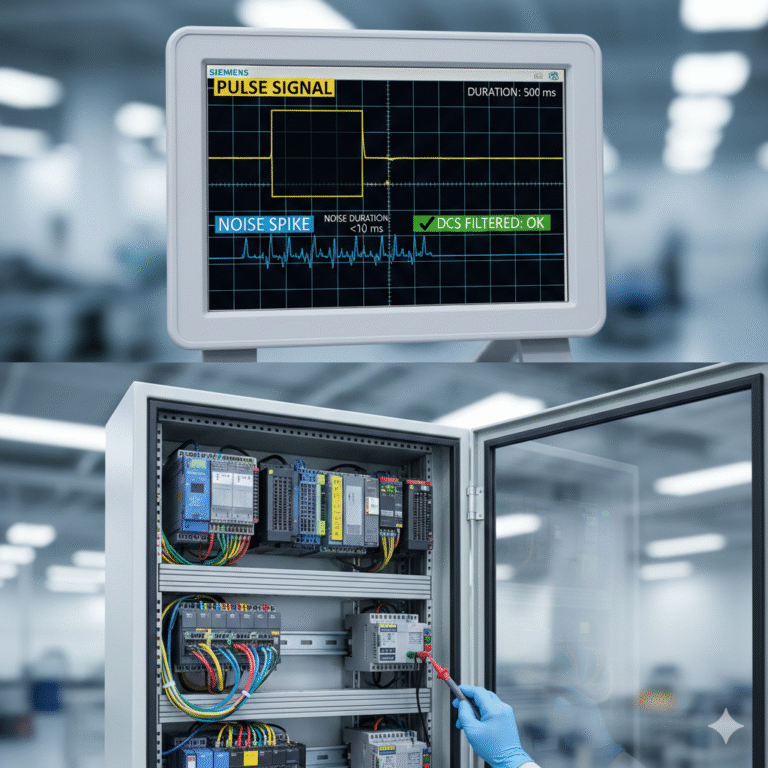
1.2 Anti-Interference Considerations
Pulse signals must be immune to field noise caused by motors, VFDs, long cable runs, etc. Therefore:
Pulse width must be longer than typical noise spikes (noise pulses are often <10 ms).
DCS filtering functions (debounce, delay-on, confirmation timers) should be applied.
1.3 One-Time Action Requirement
A pulse should only trigger one event, not maintain or repeat it.
Example: If a pulse is used to start a pump, the pump should continue running after the pulse ends. The pulse must not be long enough to cause double-start or repeated commands.
1.4 DCS Scan Cycle Adaptation
If pulse duration is shorter than the DCS scan cycle, the system may miss it.
Rule of thumb:
Pulse time ≥ 1.5 × DCS scan cycle
Example:
DCS scan cycle: 20 ms
Minimum pulse width: 30 ms
2. Application Scenarios for Short vs. Long Pulses
Pulse duration is typically divided into two categories (actual values vary by system):
Short pulse: 10–100 ms
Long pulse: 100 ms – several seconds
Choosing between them depends on device response time and logic requirements.
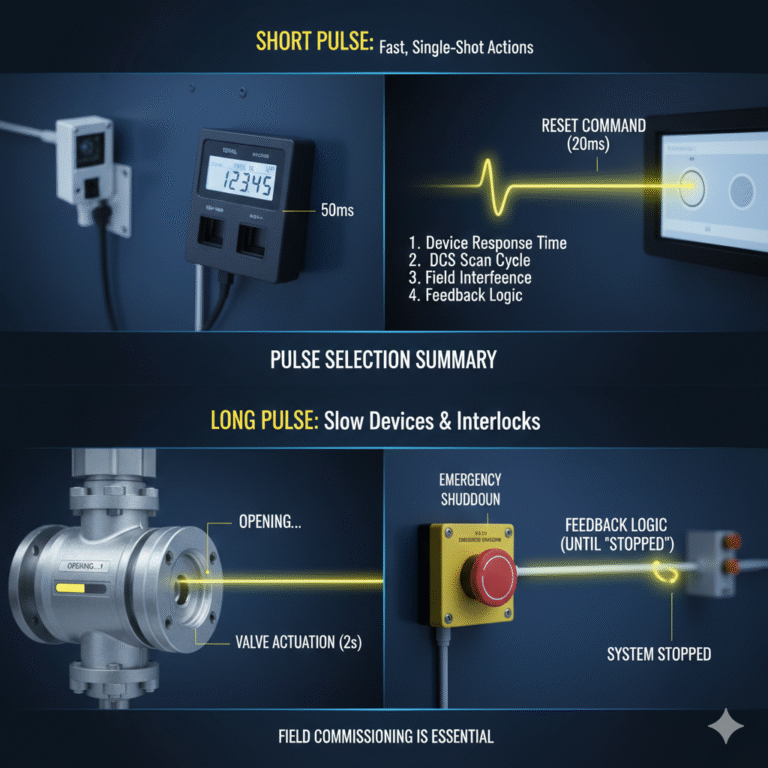
2.1 When to Use Short Pulses
Short pulses are used when fast triggering is required and repeated activation must be avoided.
Typical scenarios:
(1) Flowmeter or counter pulses
Used for:
Flow totalization
Conveyor belt weighing
Speed measurement
Short pulses avoid multiple counts caused by long signal durations.
(2) Reset or acknowledge commands
Examples:
PID mode switch reset
Alarm acknowledge
System reset commands
Short pulses guarantee single execution and avoid logic oscillation.
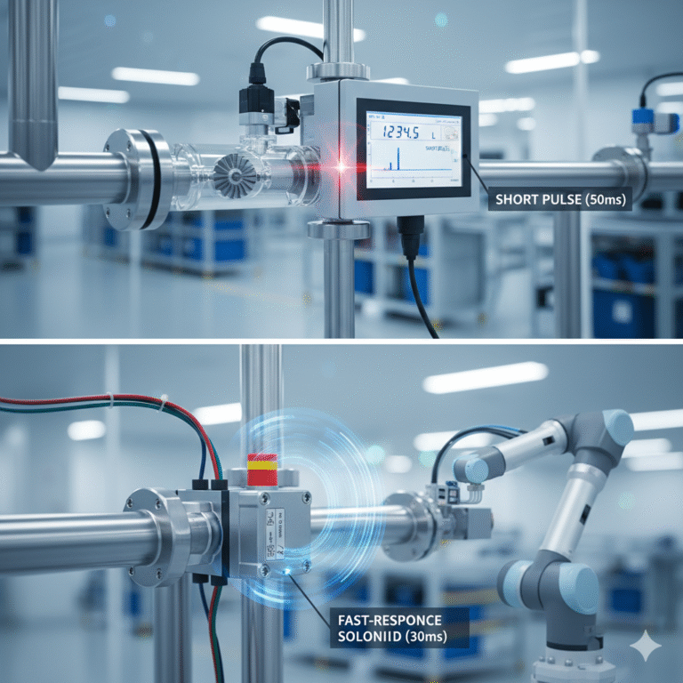
(3) Fast-response devices
Devices with reaction times <50 ms:
Small solenoid valves
Photoelectric sensors
Proximity switches
A short pulse is enough for proper recognition.
2.2 When to Use Long Pulses
Long pulses are required when the controlled equipment responds slowly or the system must ensure the command is fully received.
Typical scenarios:
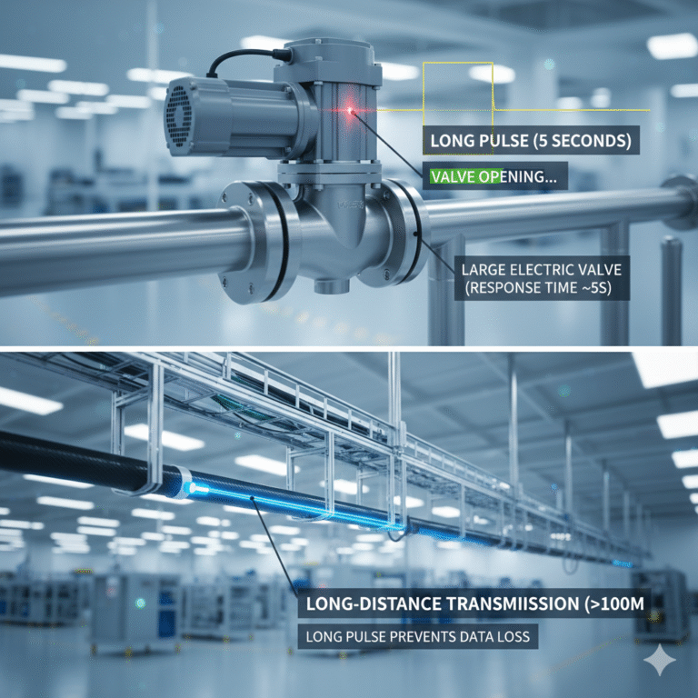
(1) Large valve open/close commands
Large pneumatic or electric valves often require:
200 ms–1 s to begin motion
Up to several seconds to reach full stroke
Pulse must cover the minimum response time (e.g., 1–2 s).
(2) Interlocks requiring feedback confirmation
Example: Emergency shutdown (ESD) commands that must persist until the feedback “Stopped” is received.
If the pulse is too short, the device may fail to complete the shutdown sequence.
(3) Long-distance signal transmission
When signals travel through cables >100 m, attenuation or minor delays may occur.
Long pulses reduce the risk of lost or unrecognized commands.
3. How to Determine the Proper Pulse Duration
Pulse duration must be determined based on equipment specifications, system characteristics, and site conditions. The following method is recommended.
3.1 Use the Device’s “Minimum Response Time”
This is the shortest time the device needs to detect a command and begin acting.