In industrial fluid control systems, the velocity of the medium downstream of a control valve is a key factor affecting system stability, equipment service life, noise generation, and overall operating efficiency. Selecting an appropriate velocity range requires considering the fluid type, thermodynamic conditions, pipeline configuration, and valve design. There is no single universal value, but there are widely accepted engineering reference ranges.
This document summarizes typical recommended downstream velocity ranges for different media, along with considerations and selection guidance.
1. Why Downstream Velocity Matters
Excessive downstream velocity may lead to:
Increased aerodynamic noise or cavitation noise
Accelerated erosion of valve trim and downstream piping
Higher pressure loss and energy consumption
Flow-induced vibration and potential mechanical fatigue
Overly low velocity may result in:
Unstable control due to sensitivity reduction
Particle settling (for slurry or suspended solids)
Poor mixing or heat transfer efficiency
Therefore, selecting a balanced velocity range is essential for reliable valve operation.
2. Recommended Downstream Velocity Ranges
| Medium Type | Recommended Velocity After Control Valve | Notes |
|---|---|---|
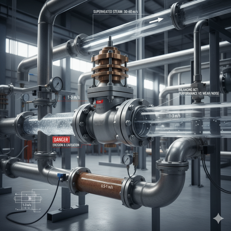
| Clean Liquids | 1–3 m/s | General industrial applications |
| High-Viscosity Liquids | 0.5–1.5 m/s | To reduce pressure loss and control instability |
| Liquids with Solid Particles (Slurry) | 0.5–1.5 m/s | Avoid excessive erosion; consider pipe material hardness |
| Volatile / Flash-Prone Liquids | < 1 m/s | Use anti-cavitation or multi-stage trim if pressure drop is high |
| Saturated Steam | 20–40 m/s | Balance noise and pressure loss |
| Superheated Steam | 30–60 m/s | Lower density allows higher velocities |
| General Industrial Gas | 20–60 m/s | Avoid nearing sonic velocity |
| Two-Phase Flow | Case-specific | Often kept lower due to vibration and erosion risks |
Core Engineering Principle:
Higher density → lower recommended velocity; lower density → higher acceptable velocity.
For gases and steam, always avoid sonic and choked flow conditions.
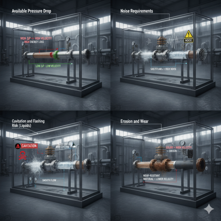
3. Key Factors Influencing Velocity Selection
Available Pressure Drop
Higher velocity corresponds to greater pressure loss. Evaluate system ΔP margin.Noise Requirements
Gas and steam flow above 60 m/s typically generates high aerodynamic noise.Cavitation and Flashing Risk (Liquids)
When valve outlet pressure falls below vapor pressure, special anti-cavitation valve trims are required.Erosion and Wear
Fluids containing solids or droplets require lower velocities and wear-resistant materials.Valve and Piping Configuration
Sudden expansion, reducers, elbows near the valve outlet can amplify turbulence.
4. Practical Engineering Rules of Thumb
Liquids:
Maintain 1–3 m/s for most installations. Lower the velocity if cavitation risk exists.Steam and Gas:
Maintain 20–60 m/s depending on pressure level. Monitor noise and vibration.Flashing or Cavitation Conditions:
Reduce velocity + use specialized valve trim (multi-stage, cage-guided, angle valve).
5. Quick Memory Formula (Technical Personnel Shortcut)
“1–3 for liquids, 20–60 for steam/gas, and keep flashing liquids below 1.”
This simple heuristic fits >85% of real industrial control valve applications.
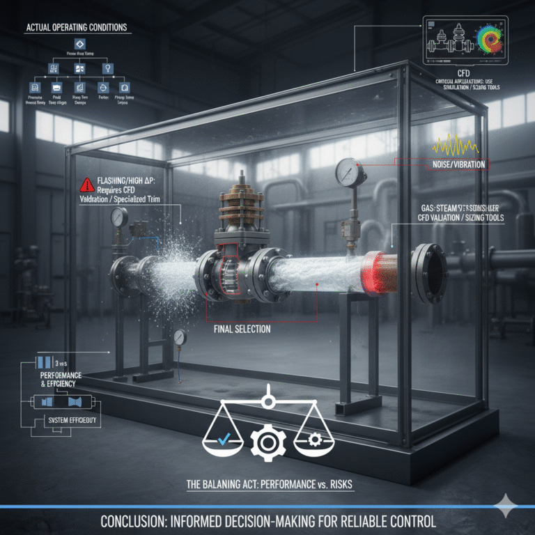
6. Conclusion
Selecting an appropriate downstream velocity after a control valve is a balancing act between performance, noise, erosion resistance, and system efficiency. While standard reference ranges provide useful guidance, final selection should always consider:
Actual operating pressure/temperature
Fluid properties
Valve internal trim design
Piping layout and downstream process requirements
For critical or complex applications (especially high ΔP or flashing conditions), velocity assessment should be validated using manufacturer sizing tools or CFD simulation.