1. Principle of Thermocouples and Their Resistance Characteristics
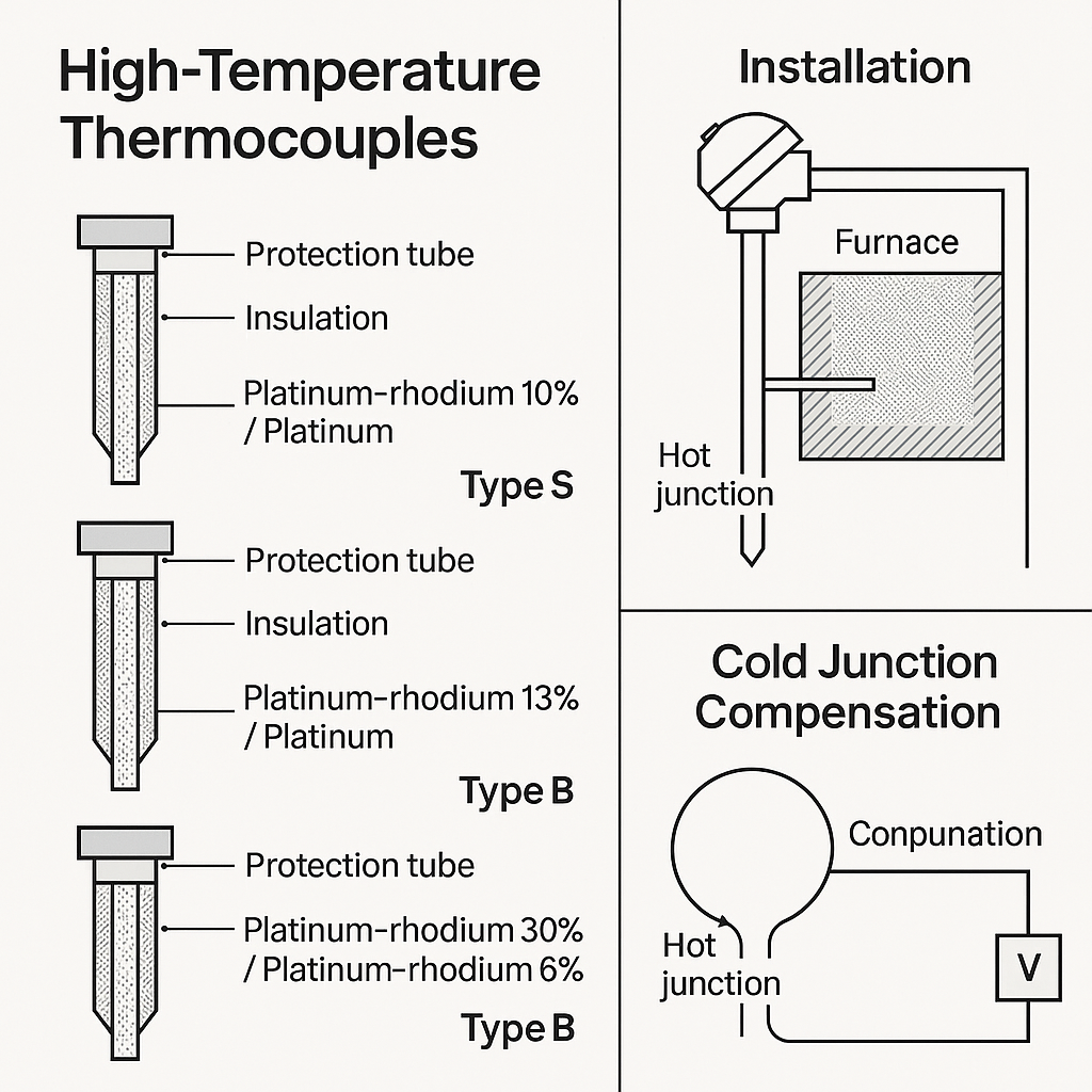
A thermocouple is a commonly used sensor in industrial temperature measurement. Its core principle is based on the Seebeck effect: two different metal wires (the thermoelectrodes) are connected to form a closed loop. When the two ends are at different temperatures, a thermoelectric potential (in millivolt levels) is generated. By measuring the thermoelectric potential, the temperature can be deduced.
It is important to note that the key measurement parameter of a thermocouple is the thermoelectric potential, not the resistance. However, the thermoelectric potential transmission is closely related to the electrical resistance characteristics of the electrodes, especially in high-temperature or long-distance measurement scenarios. Changes in resistance can affect signal accuracy.
2. Variation of Thermocouple Wire Resistance with Temperature
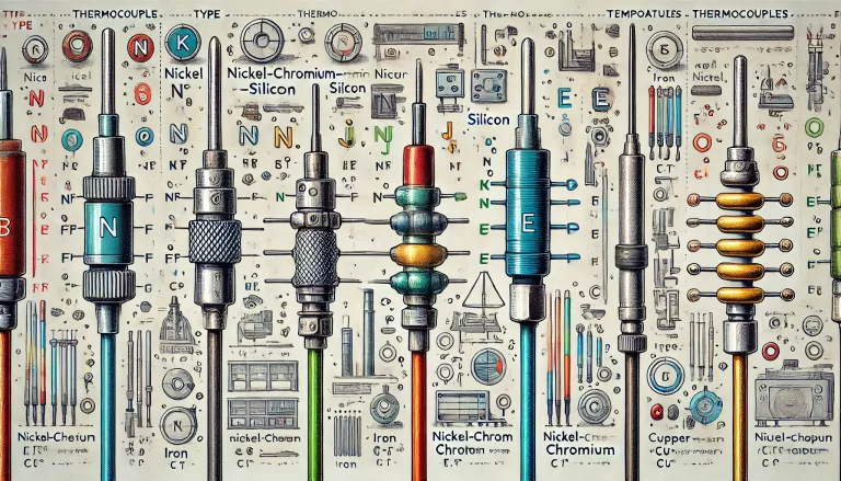
As temperature increases, the resistance of thermocouple wires generally increases, primarily determined by the material’s temperature coefficient of resistance (α). Different thermocouple types, due to the variation in electrode materials, exhibit distinct resistance change characteristics. Common types and their behavior are as follows:
2.1 Resistance Characteristics of Common Thermocouple Materials
| Thermocouple Type | Thermoelectrode Material | Resistance at 20°C (μΩ·m) | Temperature Coefficient (α, 1/°C) | Typical Operating Temperature Range |
|---|---|---|---|---|
| K-Type | Nickel-Chromium / Nickel-Silicon | 0.61 (Ni-Cr), 0.28 (Ni-Si) | 0.004 (Ni-Cr) | -200°C ~ 1300°C |
| J-Type | Iron / Constantan | 0.10 (Fe), 0.49 (Constantan) | 0.005 (Fe) | -40°C ~ 750°C |
| T-Type | Copper / Constantan | 0.017 (Cu), 0.49 (Constantan) | 0.0039 (Cu) | -200°C ~ 350°C |
| S-Type | Platinum-Rhodium10 / Pure Platinum | 0.19 (Pt-Rh), 0.098 (Pt) | 0.00392 (Pt) | 0°C ~ 1600°C |

2.2 Resistance Change with Temperature
Linear Growth: Within the working temperature range, the resistance of most thermocouple materials increases nearly linearly with temperature, as described by the equation:
where
is the resistance at temperature
is the resistance at 0°C, and
,
are material constants (with
being negligible at low temperatures, thus approximating linearity).
Non-linear Behavior at High Temperatures: Some materials, such as iron, exhibit abnormal resistance change rates near their Curie point. This requires specific analysis based on the material characteristics.
3. Determining the Normal Resistance Range
The “normal resistance range” of a thermocouple wire depends on the material type, operating temperature, wire length, and the system’s allowable measurement error. The core principle is that resistance changes should not cause the thermoelectric potential measurement error to exceed the instrument’s accuracy level, usually ±0.5% to ±1%.
3.1 Normal Resistance Ranges for Common Thermocouple Types
| Thermocouple Type | Maximum Operating Temperature | Standard Resistance at 0°C (250mm length) | Maximum Allowable Resistance at Max Temp | Resistance Change Rate (relative to 0°C) |
|---|---|---|---|---|
| K-Type | 1300°C | 1.5 ~ 2.5Ω | ≤ 10Ω (due to oxidation of Ni-Cr) | ≤ 400% |
| J-Type | 750°C | 1.0 ~ 2.0Ω | ≤ 6Ω (iron is prone to oxidation) | ≤ 300% |
| T-Type | 350°C | 0.5 ~ 1.0Ω | ≤ 2Ω (copper’s high resistance coefficient) | ≤ 200% |
| S-Type | 1600°C | 1.0 ~ 3.0Ω | ≤ 15Ω (platinum-rhodium’s good stability) | ≤ 500% |
3.2 Key Influencing Factors
Wire Length: For long-distance measurements (e.g., over 10 meters), the resistance of the wires must be compensated. The total resistance should typically be within 1/1000 of the instrument’s input impedance (e.g., for an input impedance of 10MΩ, the wire resistance should be ≤ 10Ω).
Material Purity: Industrial-grade thermocouples may allow some impurities that cause resistance fluctuations. For example, K-type thermocouples generally have a temperature deviation of ≤ ±0.2Ω/m at room temperature.
Oxidation and Aging: At high temperatures, the electrode materials (e.g., K-type nickel-chromium wires) can oxidize, causing the resistance to increase abnormally. The annual increase in resistance should typically be ≤ 5%.

4. Identifying and Handling Abnormal Resistance
4.1 Typical Manifestations of Abnormal Resistance
Exceeding Maximum Allowable Resistance: For example, if a K-type thermocouple exceeds 10Ω at 1300°C, it may be due to oxidation or material degradation.
Sudden or Unstable Resistance: If the resistance fluctuates by more than ±0.5Ω with stable temperature, it could indicate poor contact, damaged insulation, or a broken wire.
High Resistance at Low Temperatures: For example, a T-type thermocouple showing resistance greater than 2Ω at 20°C might have wire corrosion or contamination.
4.2 Handling Suggestions
Regular Inspections: Measure the resistance at room temperature using a high-precision multimeter and compare it with historical data. If deviations exceed ±10%, recalibration or replacement is required.
High-Temperature Protection: To reduce oxidation-induced resistance increase, K-type, J-type, and other easily oxidized thermocouples can be protected with ceramic sheaths or inert gas.
Compensating Wires: Ensure that the compensation wire matches the thermocouple material (e.g., K-type thermocouples should be paired with K-type compensation wires) to avoid additional resistance errors.
5. Conclusion
The resistance of thermocouple wires increases systematically with temperature. The normal range should be determined based on the material type, operating temperature, and system accuracy requirements. In practice, it is recommended to:
Focus primarily on the thermoelectric potential measurement, while regularly monitoring resistance changes as a supplementary indicator of performance.
Refer to the resistance-temperature curves provided by manufacturers or industry standards (e.g., IEC 60584) for different thermocouple types.
Control wire length, material purity, and environmental protection to ensure that resistance changes stay within the instrument’s compensable range, ensuring accurate temperature measurements.
For detailed parameters of specific thermocouple models, refer to the manufacturer’s technical manuals or use WPS table tools to build a resistance-temperature calculation model for dynamic range evaluation.