This guide provides detailed instructions for using a digital multimeter in typical industrial scenarios, such as current loop measurement, RTD and thermocouple testing, and voltage measurements. Emphasis is placed on safety, accuracy, and practical steps for on-site diagnostics.
2. Measuring 4–20 mA Current Loop Signals
Method 1: Break-Point Series Measurement
Ensure the loop is powered and stable.
Disconnect one of the signal wires between the transmitter and control system.
Set the multimeter to the DC current range (typically 200 mA) and insert the red probe into the mA jack.
Connect the probes across the break in series.
If the reading is negative, reverse the probes.
⚠ Warning: Never directly connect the probes across the transmitter terminals in current mode — this can cause internal fuse blowout or meter damage.
Method 2: Extra Terminal Tapping
Without removing wires, locate a third (spare) terminal on the transmitter.
Set the meter to mA range.
Connect the red probe to the transmitter’s negative terminal, and the black probe to the third terminal.
Read the output current.
3. RTD (Pt100) Resistance Measurement & Diagnosis
Three-wire RTD Circuit Check
Set the multimeter to resistance (Ω) mode.
Verify meter calibration: short probes and confirm 0Ω.
Disconnect all three RTD wires at the terminal block.
Visually inspect for corrosion, leaks, or mechanical damage.
Use resistance mode to test continuity:
Standard thermocouple: <2Ω
Mineral insulated cable: <50Ω
1kΩ: Likely broken
No Thermoelectric Signal
If display remains fixed or maximum value shows:
Check for open circuit
Inspect internal junction for mechanical or heat damage
Weak/Incorrect Signal
Possible causes:
Improper insertion depth
Scaling or corrosion on protection tube
Moisture ingress
Electrode thinning or color change
Poor weld at measuring junction
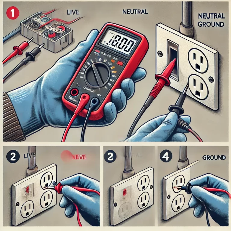
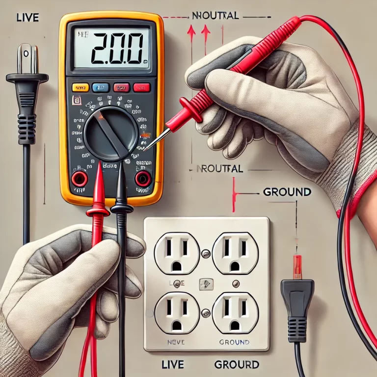
5. Voltage Measurement
DC Voltage
Black probe to COM, red to V/Ω.
Set meter to V– (DC), select appropriate range.
Connect across power source/load.
AC Voltage
Same probe setup.
Set meter to V~ (AC).
Measure across terminals.
Caution:
Always start with highest range if voltage level is unknown.
“1” on display = Overrange → switch to higher range.
Avoid inputting voltages beyond rated limits to prevent internal damage.
Do not touch probe metal during high-voltage tests.
Beware of false readings due to external electromagnetic interference.
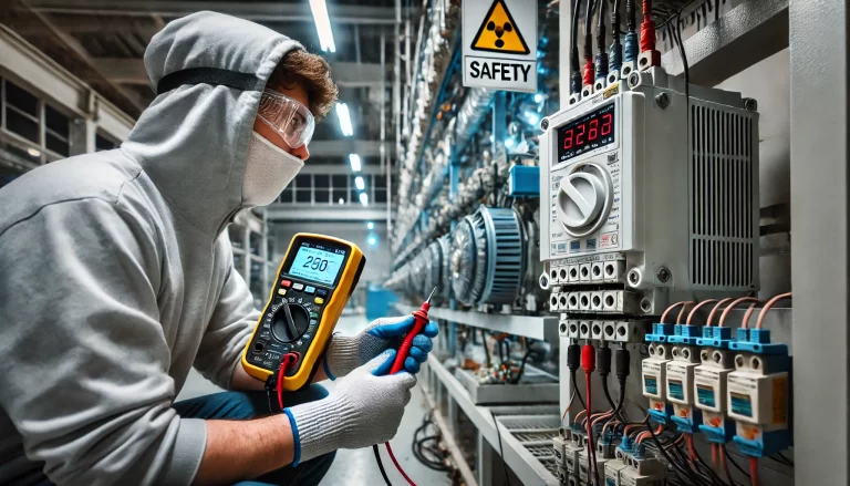
6. General Safety Notes
Never use current mode across voltage sources.
Observe polarity and range settings.
Avoid measuring in wet or explosive environments.
Ensure test leads and multimeter are in good condition.
Always isolate the circuit when in doubt.
7. Conclusion
Proper use of a digital multimeter enhances diagnostic accuracy and ensures operator safety. Familiarity with these methods helps technicians quickly detect faults in transmitters, RTDs, and thermocouples across industrial installations.