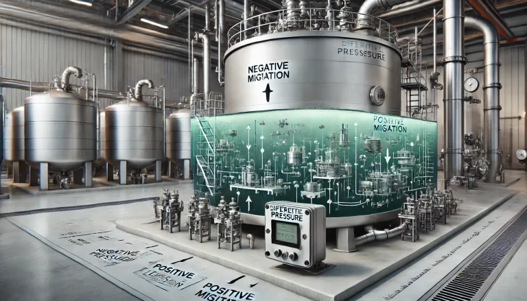
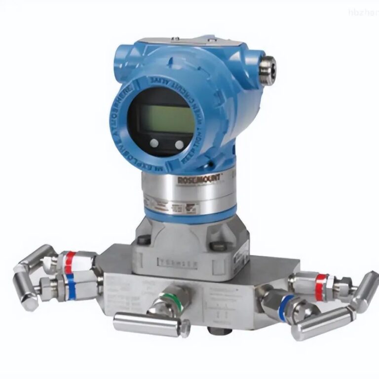
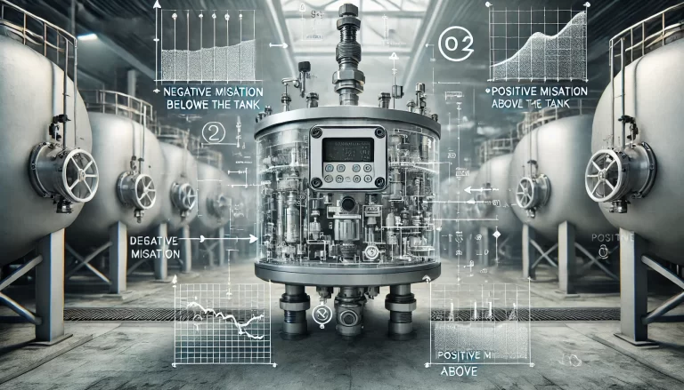
In industrial settings, differential pressure flow meters are essential for accurate measurement and process control. However, cases of no indication often arise, even when other equipment seems to be functioning normally. This article will analyze two case studies to uncover common issues and solutions, followed by a comprehensive guide to troubleshooting and maintenance.

Case Study 1: No Indication for Xylene Flow after Maintenance
Background:
After maintenance in the benzene isolation workshop, the feed flow of ortho-xylene showed no indication on the differential pressure flow meter, despite the oxidation reactor’s temperature reflecting material inflow. A secondary rotameter in the system indicated stable flow.
Analysis:
Initial Investigation:
Instrumentation technicians thoroughly inspected the transmitter and the orifice plate measurement system, finding no apparent issues.
Temporary flow indication appeared after draining the transmitter’s discharge line but disappeared again shortly thereafter.
Root Cause Identification:
Sampling from the orifice plate’s pressure taps revealed a distinct layering in the fluid.
Laboratory analysis confirmed severe water contamination in the xylene, with water content nearing 30%.
The density difference between xylene and water (~100 g/L) created a counteracting pressure differential that nullified the meter’s reading.
Solution:
The workshop was notified to resolve the water contamination in the xylene feedstock.
Once addressed, the flow meter resumed normal operation.

Case Study 2: No Indication for Fluid Supply to a Sulfurization Bed
Background:
Operators reported no flow indication for the water supply to the gas bag of a sulfurization bed. However, observations of the gas bag’s liquid level and reaction temperature suggested water was indeed flowing.
Analysis:
Initial Inspection:
Technicians drained both positive and negative pressure chambers of the differential pressure transmitter.
The negative pressure chamber produced normal outputs, ruling out transmitter malfunction.
The positive pressure chamber revealed partial blockage in the piping.
Further Investigation:
Sequential pipeline checks with compressed air isolated the blockage to the orifice plate’s primary pressure tap and chamber.
The root cause was a clogged needle-type stop valve, unsuitable for maintenance and cleaning.
Solution:
The clogged valve was replaced with a ball valve to facilitate easier cleaning and maintenance.
Post-replacement, the flow meter functioned normally.

Common Causes of No Indication in Differential Pressure Flow Meters
1. Instrumentation Issues:
Sampling valves not opened.
Blocked impulse lines.
Inadequate condensation of steam in condensate systems.
Open discharge valves.
Power supply or connection cable faults.
Transmitter component failure.
2. Process Issues:
Actual absence of flow in the pipeline.
Troubleshooting Steps
Step 1: Visual Inspection
Check display indicators on both the instrument and transmitter.
If readings are below zero or the LCD shows no display, inspect power sources.
Confirm power switches and fuses are functional, and cables are intact.
Step 2: Voltage and Current Measurements
Measure the 24V DC power supply voltage with a multimeter.
Verify voltage at transmitter terminals (18-23V).
Zero voltage indicates an open or short circuit in the measurement loop.
If no current is detected, inspect:
Loose or corroded signal terminals.
Input/output currents at safety barriers to locate faults.
Step 3: Verify Transmitter Configuration
Ensure correct range settings on new or replaced transmitters.
Check that smart transmitter parameters are properly configured.
Verify that transmitters are not in a fixed 4mA output mode.
Step 4: Impulse Line and Valve Inspection
Inspect impulse lines for blockages or leaks.
Test sampling and discharge valves to ensure proper operation.
Simulate pressure differentials by quickly opening and closing discharge valves to test transmitter response.
Step 5: Process Verification
Ensure flow exists in the pipeline.
Investigate upstream and downstream process parameters for anomalies.

Maintenance Recommendations
Design Improvements:
Use ball valves for primary pressure taps to simplify blockage clearance.
Routine Inspections:
Regularly inspect impulse lines for debris and wear.
Periodically verify transmitter calibration and settings.
Training and Documentation:
Train personnel in identifying and addressing common issues.
Maintain comprehensive records of system configurations and past issues.
By following these troubleshooting steps and implementing proactive maintenance strategies, operational disruptions due to differential pressure flow meter failures can be minimized, ensuring reliable process control.
