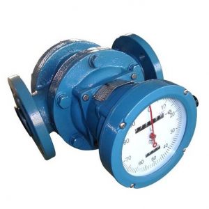
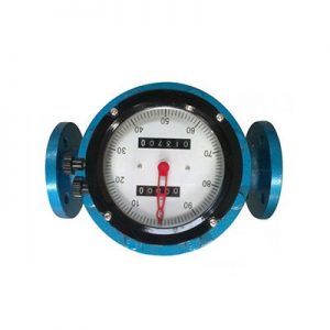
The oval gear flowmeter is mainly composed of a metering housing, an oval gear rotor, and transmission components. An instrument used for continuous or intermittent measurement and control of liquid flow in pipelines.
The structure and working principle of the oval gear flowmeter
The main mechanical measurement part of the oval gear flowmeter is the shell and the pair of elliptical gears that mesh with each other in the shell. They and the cover form a closed fluid metering space.
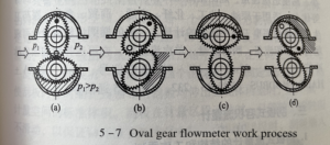
The fluid inlet and outlet are located on the plane of the two oval gear axes. On both sides of the housing, as shown in Figure 5-7 (a), the lower gear rotates counterclockwise under the action of the pressure difference on both sides, which is the driving wheel; the upper gear does not rotate due to the equal pressure on both sides Torque is the driven wheel, which is driven by the lower gear and rotates in a clockwise direction. When the fluid enters the flowmeter, the existence of the inlet and outlet pressure difference p=P1-P2 makes the elliptical gear rotate under the action of torque.
In the position shown in Figure 5-7 (a), since P1>P2, under the action of the resultant torque generated by P1 and P2, the fluid in the metering space formed by gear A and the housing is discharged to the outlet, and Drive wheel B to rotate clockwise.
At this time, A is the driving wheel and B is the driven wheel; at the position shown in Figure 5-7 (b), both wheels A and B produce torque, and the two wheels continue to rotate, and gradually seal the fluid in the metering space formed by wheel B and the housing: when it continues to the position shown in Figure 5-7 (c), P1 and P2 act on the torque on wheel A to be zero, while wheel B The inlet pressure is greater than the outlet pressure, generating torque, making wheel B become the driving wheel and continuing to rotate clockwise, and at the same time, the fluid in the metering space formed by wheel B and the housing is discharged to the outlet.
In such a reciprocating cycle, the two oval gears A and B are alternately driven, and the crescent-shaped metering space fixed between the elliptical gear and the housing is used as the unit of measurement, and the fluid at the inlet is continuously sent to the outlet.
Figure 5-7 shows only the case where the oval gear rotates a quarter of a turn, and the corresponding amount of fluid discharged is a crescent-shaped cavity volume. Therefore, one cycle action discharges the flow volume of the four crescent-shaped cavities enclosed by the gear and the shell wall. This volume is called the flow volume. The “circulation volume” of the meter. If the number of revolutions of the oval gear is n. The flow rate through the oval gear flowmeter is Q =4V0n=qn It can be seen that For an oval gear flowmeter with a known displacement value q, as long as the maximum number of revolutions n is measured, the flow rate through the flowmeter can be determined.
The rotation of the oval gear is transmitted to the counter through the magnetic seal coupling and the transmission reduction mechanism to directly indicate the total amount flowing through the flowmeter. If the sending device is attached, it can be equipped with a display instrument to realize remote transmission indicating instantaneous flow or cumulative flow.