
A practical guide to working principles, installation, calibration, HART communication, and common faults
A magnetostrictive level transmitter is often selected for applications requiring high measurement accuracy, reliable liquid level monitoring, and interface detection. However, even a high-accuracy instrument can produce incorrect readings when its float becomes stuck, the probe is bent, or the transmitter is incorrectly configured.
Imagine a situation in a storage tank: the DCS continuously displays 3.42 m for three days, even though the tank is being filled. The maintenance team initially suspects an electronic failure and considers replacing the entire transmitter.
After inspecting the instrument, however, the actual problem becomes clear. Wax has accumulated around the probe, preventing the float from moving freely.
The transmitter is not necessarily defective. It is simply reporting the position of a float that cannot move.
This is an important lesson for instrumentation technicians: Before replacing a level transmitter, check its mechanical condition, installation, float movement, and configuration.
In this guide, we will explain how magnetostrictive level transmitters work, how to install and calibrate them, how to use HART communication, and how to troubleshoot common problems in industrial applications.
1. How Does a Magnetostrictive Level Transmitter Work?
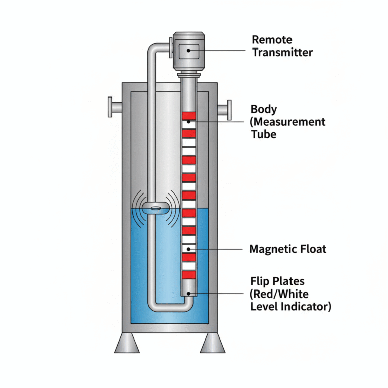
Unlike radar and ultrasonic level transmitters, a magnetostrictive level transmitter does not measure the reflection time of an electromagnetic or acoustic signal.
Instead, it measures the position of a magnetic float by detecting the propagation time of a torsional stress wave along a waveguide.
Its working principle is based on the Wiedemann effect.
The measurement process
The main measurement process consists of five steps:
Step 1: Generate an electrical current pulse
The electronic transmitter generates a short electrical current pulse and sends it through a magnetostrictive waveguide inside the probe.
This current creates a circular magnetic field around the waveguide.
Step 2: Generate a magnetic field from the float
A permanent magnet is installed inside the float. As the liquid level changes, the float moves up or down along the measuring probe.
The permanent magnet produces a magnetic field along the probe.
Step 3: Generate a torsional stress wave
When the electrical pulse reaches the position of the float magnet, the interaction between the two magnetic fields generates a torsional stress wave in the waveguide.
This phenomenon is known as the Wiedemann effect.
Step 4: Detect the returning wave
The torsional wave travels along the waveguide toward the transmitter electronics, where a sensing element detects it and converts it into an electrical signal.
Step 5: Calculate the float position
The transmitter measures the time between generating the electrical pulse and detecting the torsional wave.
The distance is calculated using the propagation time and the calibrated wave velocity.
Simplified relationship:
Distance = Wave Velocity x Propagation Time
The actual transmitter also applies its factory calibration data and internal signal-processing algorithms.
Why is magnetostrictive measurement highly accurate?
The measurement principle does not depend on the dielectric constant of the liquid, unlike many radar measurement applications.
It is also generally less affected by foam, vapor, and changes in liquid temperature or pressure than several other level measurement technologies.
However, the measurement still depends on the correct mechanical movement and magnetic coupling of the float.
This is why probe contamination, float damage, incorrect float selection, and mechanical deformation must be taken seriously.
2. Main Components of a Magnetostrictive Level Transmitter
A typical magnetostrictive level transmitter consists of five main components.
2.1 Transmitter Head
The electronic housing contains the measurement circuit, signal-processing electronics, and output circuitry.
Its main functions include:
- Generating electrical excitation pulses.
- Detecting and processing torsional wave signals.
- Calculating float position.
- Providing 4-20 mA output.
- Supporting HART communication on applicable models.
- Displaying measured values and diagnostic information.
Depending on the manufacturer, the transmitter may have a single-compartment or dual-compartment housing.
2.2 Measuring Probe and Waveguide
The measuring probe houses the magnetostrictive waveguide and provides mechanical protection.
Common probe materials include stainless steel 316L and special alloys such as Hastelloy C-276, depending on the application.
The probe is in direct contact with the process liquid, so material compatibility is essential.
Potential problems include:
- Wax accumulation.
- Scale and deposits.
- Chemical corrosion.
- Mechanical deformation.
- Damage caused by strong incoming liquid flow.
2.3 Magnetic Float
The float contains a permanent magnet and moves along the probe according to the liquid level.
It is the main moving component of the instrument.
Different float designs are available for different liquid densities, operating conditions, and measurement applications.
Common designs include spherical floats and cylindrical floats.
The float must be correctly selected according to the manufacturer’s specifications.
Its buoyancy depends on its weight, volume, and the density of the measured liquid.
If the float is too heavy for the liquid, it may sink and fail to follow the liquid surface.
2.4 Damping End
The lower end of the probe normally incorporates a damping or signal-absorption structure.
Its purpose is to reduce unwanted reflections and interference associated with the torsional wave.
It also forms part of the mechanical structure of the probe.
2.5 Optional Temperature Measurement
Some magnetostrictive level transmitters can incorporate multiple temperature sensing points.
Depending on the design, these may be used to measure temperature at different positions in the tank.
The collected temperature data can support average temperature calculation and inventory management applications.
Some systems also use temperature information for volume correction, provided the appropriate configuration and calculation method are available.
3. Installation Requirements and Common Mistakes
Correct installation is essential for stable and accurate measurement.
Even a high-performance magnetostrictive level transmitter may produce unreliable readings if its probe is installed incorrectly.
3.1 Keep the Probe Properly Aligned
For a conventional top-mounted installation, the probe should be installed vertically.
A tilted probe can cause the float to rub against the measuring tube, increasing friction and potentially preventing free movement.
The allowable installation angle must follow the manufacturer’s instructions.
3.2 Check the Float Orientation
Some floats have a marking such as TOP to indicate the correct installation direction.
The marking must face upward when specified by the manufacturer.
Incorrect float orientation can affect magnetic coupling and measurement performance.
3.3 Avoid Direct Incoming Flow
When the transmitter is installed near a tank inlet, the incoming liquid may directly impact the probe or float.
This can cause:
- Float movement instability.
- Probe vibration.
- Mechanical deformation.
- Unstable output signals.
Whenever possible, install the probe away from strong incoming flow, agitators, and other sources of mechanical interference.
3.4 Support Long Measuring Probes
Long probes may require additional mechanical support, depending on their diameter, length, tank geometry, and process conditions.
A long unsupported probe can bend under flow forces or vibration.
Probe deformation may cause the float to become stuck or produce measurement errors.
Always check the manufacturer’s recommendations for bottom supports or guide structures.
3.5 Consider Side-Mounted Installation
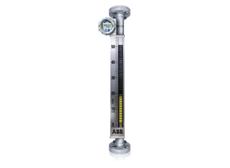
Some magnetostrictive transmitters are designed for side-mounted installation, often alongside a magnetic level gauge.
In this arrangement, the transmitter may work with the magnetic float inside the level gauge chamber.
An important requirement is that the transmitter’s measurement zero and full-scale references must be correctly aligned with the level gauge.
Otherwise, the displayed level may have a constant offset.
4. Local Configuration and Commissioning
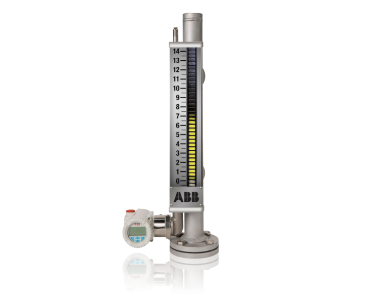
Different manufacturers use different display interfaces and configuration procedures.
Some transmitters have a local LCD and push buttons, while others use LEDs and configuration switches.
Before commissioning, technicians should confirm the exact model and consult its instruction manual.
4.1 Check the Status Indicators
On models equipped with status LEDs, the indicator may provide information about normal operation, warnings, or faults.
For example, some models use:
- Green LED: Normal operation.
- Flashing red LED: Warning or abnormal condition.
- Steady red LED: Fault condition.
These indications are not universal. Always refer to the manufacturer’s diagnostic table.
4.2 Check the Basic Configuration
Before adjusting the measuring range, confirm:
- The configured lower range value.
- The configured upper range value.
- The actual mechanical zero position.
- The actual mechanical full-scale position.
- The selected output range.
- The alarm current configuration.
A common mistake is changing the output range without checking the actual installation reference.
4.3 Isolate Automatic Control During Calibration
When calibrating a 4-20 mA output, the loop current may change significantly.
If the signal is connected to an automatic control loop, this change may cause a control valve or pump to operate unexpectedly.
Before calibration, place the associated control loop in manual mode or otherwise isolate the automatic control function according to the site’s safety procedures.
This is particularly important in chemical plants, tank farms, and other process installations.
5. HART Communicator: Configuration and Troubleshooting
Many magnetostrictive level transmitters support HART communication in addition to their analog 4-20 mA output.
A HART 475 Field Communicator can be used with compatible transmitters to read process variables, adjust configuration parameters, and perform diagnostic checks.
5.1 Basic HART Wiring
For a typical two-wire 4-20 mA transmitter, the HART communicator is connected in parallel with the current loop.
The loop must provide sufficient communication impedance.
A typical HART loop uses a load resistance of approximately 250 ohms, although the actual acceptable range depends on the transmitter, communicator, power supply, and loop configuration.
If the existing loop resistance is insufficient, an additional resistor may be required.
Always verify the wiring diagram and minimum operating voltage before connecting the communicator.
5.2 Common Configuration Tasks
Typical HART configuration functions include:
| Task | Purpose |
|---|---|
| Read PV | Check the current measured level |
| Set Lower Range Value | Configure the 4 mA measurement point |
| Set Upper Range Value | Configure the 20 mA measurement point |
| Change Measurement Range | Adjust the configured measurement span |
| Sensor Trim | Correct the displayed measurement when supported |
| DAC Trim | Adjust the analog output current |
| Alarm Configuration | Set the fault current behavior |
| Loop Test | Check the DCS input and signal transmission |
The available functions depend on the transmitter model and its HART device description.
Important: HART command numbers and menu structures are not universal across all magnetostrictive transmitters. Always use the correct DD/EDD file and the manufacturer’s operating instructions.
5.3 Understand Alarm Current Behavior
A transmitter may be configured to respond to an internal fault in several ways.
Common options include:
- High alarm current.
- Low alarm current.
- Hold last value.
The exact current values depend on the device configuration and applicable specifications.
For example, a transmitter configured to hold its last valid value may continue sending an apparently stable signal even when a fault has occurred.
This can make a genuine instrument fault look like a stuck float.
For critical applications, the alarm strategy should be coordinated with the DCS configuration and site safety requirements.
6. Empty and Full Calibration: Get the Float Position Right First
Calibration of a magnetostrictive level transmitter is fundamentally different from radar calibration.
A radar transmitter measures the distance between its reference point and the liquid surface.
A magnetostrictive transmitter measures the position of the magnetic float along the probe.
Therefore, calibration must begin with the correct physical reference positions.
6.1 Confirm the Mechanical Zero Position
Before calibration, check the actual lowest operating liquid level.
The tank may have a dead volume below the required measurement range.
In this case, the instrument’s mechanical zero position may not correspond to the actual process zero.
The reference point must be established according to the tank geometry and transmitter design.
6.2 Confirm the Float Can Move Freely
Move the float carefully, following the manufacturer’s maintenance instructions.
Check for:
- Wax accumulation.
- Scale deposits.
- Mechanical obstructions.
- Probe deformation.
- Incorrect float installation.
Never perform calibration with a float that cannot move freely.
Otherwise, the resulting zero and full-scale settings may be incorrect.
6.3 Set the 4 mA Point
Place the float at the intended zero-level reference position.
Use the transmitter’s local interface or HART configuration menu to set the lower range value.
The transmitter should then output 4 mA at the configured zero point.
6.4 Set the 20 mA Point
Move the float to the intended full-scale reference position.
Configure the upper range value so that the transmitter outputs 20 mA at this position.
Check the reading on the local display and compare it with the DCS indication.
6.5 Perform Zero Offset Adjustment When Necessary
If the actual tank zero position does not coincide with the probe’s original reference point, a zero offset or range adjustment may be necessary.
After changing the reference position, verify both the lower and upper range values.
Do not assume that changing one calibration parameter automatically updates all other settings.
6.6 Interface Measurement Requires Special Attention
Some magnetostrictive level transmitters can measure both the upper liquid level and the interface between two liquids.
This normally requires two appropriately designed magnetic floats:
- An upper float for the product level.
- A lower float designed for interface detection.
The float designs must match the densities of the two liquid phases.
If the density difference is insufficient for the selected float design, the interface float may not remain at a stable position.
The required density difference and float dimensions must always be confirmed with the manufacturer.
Each float measurement must also be configured and checked according to the instrument’s specific design.
7. Common Magnetostrictive Level Transmitter Faults and Troubleshooting
When a magnetostrictive level transmitter produces an abnormal reading, do not immediately replace the electronic transmitter.
Start by checking the mechanical condition, actual float position, electrical output, and configuration.
The following table summarizes common symptoms.
| Symptom | Possible Cause | Recommended Action |
|---|---|---|
| Reading remains unchanged | Float stuck due to wax, deposits, or mechanical obstruction; output configured to hold last value | Inspect float movement, clean the probe, and check alarm configuration |
| Reading remains at zero | Float has sunk, detached, or the tank is empty | Check liquid density, float condition, and actual liquid level |
| Reading remains at full scale | Incorrect float selection, float obstruction, or incorrect range configuration | Inspect float movement and verify upper range settings |
| Reading fluctuates slightly | Liquid turbulence, incoming flow, vibration, or insufficient damping | Check installation and adjust damping if supported |
| Constant measurement offset | Incorrect zero reference or range configuration | Verify mechanical reference points and recalibrate |
| Increasing error toward the upper range | Bent probe, mechanical friction, or incorrect calibration | Inspect probe straightness and float movement |
| No output signal | Power supply problem, incorrect wiring, loose terminals, or electronic failure | Check supply voltage, polarity, terminals, and loop continuity |
| DCS always displays 4 mA | Possible multidrop configuration or loop configuration issue | Check HART communication mode and transmitter output configuration |
| HART communication fails | Incorrect wiring, insufficient loop resistance, incompatible device description, or interference | Verify loop wiring, resistance, communicator compatibility, and grounding |
7.1 Reading Does Not Change
This is one of the most common problems.
Possible causes include:
- Float stuck on the probe.
- Wax or scale accumulation.
- Mechanical deformation.
- Incorrect alarm configuration.
- Actual liquid level remaining unchanged.
The first step should be to compare the physical float position with the actual tank level.
If the float is stuck, clean the probe and inspect the float.
If the float moves normally, check the output current and diagnostic status.
7.2 Reading Always Shows Zero
Possible causes include:
- The float has sunk.
- The float has detached from its intended position.
- The liquid level is genuinely at zero.
- The transmitter range has been configured incorrectly.
Check the float’s suitability for the liquid density and inspect the actual mechanical condition.
7.3 Reading Always Shows Full Scale
Possible causes include:
- Incorrect float density or design.
- Float movement obstruction.
- Incorrect upper range configuration.
- Incorrect mechanical reference position.
Check the float position before changing the transmitter parameters.
7.4 Reading Fluctuates
Unstable readings may result from liquid turbulence, agitation, vibration, or mechanical movement of the probe.
Some transmitters provide a damping function.
If available, the damping time can be adjusted according to the process conditions.
However, excessive damping can delay the response to actual level changes.
The objective is to reduce unwanted fluctuations without compromising process response.
7.5 Reading Has a Constant Offset
If the transmitter consistently reads higher or lower than the actual liquid level, check:
- Zero reference position.
- Lower and upper range values.
- Mechanical installation alignment.
- Side-mounted transmitter alignment with the level gauge.
- Previous calibration adjustments.
Correct the underlying configuration or mechanical reference rather than applying an arbitrary offset.
7.6 Reading Becomes Increasingly Inaccurate Along the Probe
If the reading is correct near the bottom but increasingly inaccurate at higher positions, inspect the measuring probe for bending or mechanical deformation.
A bent probe may cause the float to rub against the probe surface.
Check the straightness of the probe and inspect whether the float can travel freely along its full measuring range.
8. Three Real-World Maintenance Cases
Case 1: Wax Accumulation in a Heavy Oil Tank
Symptom: The DCS reading remained at 3.42 m for three consecutive days.
The tank was still receiving liquid, but the indicated level did not change.
Investigation:
During inspection, technicians found wax accumulation around the measuring probe at approximately 3.4 m.
The float was trapped by the accumulated wax and could not move upward or downward.
The transmitter continued reporting the float’s actual position.
Solution:
The instrument was removed following the site’s maintenance and isolation procedures.
The probe was cleaned, and the float was inspected.
A probe design with improved resistance to wax accumulation was considered for the application.
The transmitter was then checked and recalibrated.
Key lesson:
When the reading remains completely unchanged while other process parameters indicate that the tank level is changing, always inspect the float and probe before replacing the electronics.
Case 2: Unstable Interface Measurement in a Solvent Tank
Symptom: The liquid level measurement was normal, but the interface reading fluctuated continuously.
Investigation:
The tank contained two liquid phases.
After checking the transmitter configuration, technicians investigated the actual liquid properties.
The density difference between the two phases was approximately 0.03, which was insufficient for the selected float design.
The interface float could not maintain a stable position.
Solution:
A different float design was selected after reviewing the liquid densities and mechanical requirements.
The installation position was also reviewed to ensure that the float operated in a stable separation zone.
Damping was adjusted according to the process conditions.
Key lesson:
Successful interface measurement depends on the density difference between the liquid phases and the correct selection of the interface float.
Case 3: Nonlinear Measurement Error in a Long Probe
Symptom: A newly installed transmitter showed acceptable readings near zero and full scale, but the measurement error increased around the middle of the range.
Investigation:
The transmitter had a measuring probe approximately 4 m long.
The lower end had no additional mechanical support.
Incoming liquid flow caused the probe to bend.
Inspection showed that the probe was approximately 8 mm out of its intended straight alignment at the middle section.
The float experienced additional friction when passing through this area.
Solution:
A suitable mechanical support structure was installed.
The mounting position was also changed to reduce direct exposure to incoming liquid flow.
The probe and float were inspected, and the measurement range was checked again.
Key lesson:
For long measuring probes, mechanical stability is just as important as electronic accuracy.
9. Magnetostrictive vs. Radar vs. Guided Wave Radar vs. Ultrasonic vs. Differential Pressure

Different level measurement technologies have different strengths and limitations.
The correct choice depends on the medium, operating conditions, accuracy requirements, installation environment, and maintenance expectations.
| Technology | Main Advantages | Main Limitations | Typical Applications |
|---|---|---|---|
| Magnetostrictive | High accuracy; suitable for continuous level and selected interface applications | Requires a moving float; probe contacts the liquid; sensitive to mechanical obstruction | Storage tanks, oil products, solvents, inventory measurement |
| Guided Wave Radar | Generally suitable for applications involving vapor, foam, and some turbulent conditions | Probe may accumulate deposits; dielectric properties and application conditions matter | Process tanks, liquids, and selected solids |
| Non-Contact Radar | No moving parts in contact with the liquid; suitable for many corrosive and large-tank applications | Foam, condensation, internal obstructions, and installation geometry may affect performance | Chemical tanks, water tanks, storage vessels |
| Ultrasonic | Relatively economical and non-contact | Affected by vapor, temperature gradients, foam, and acoustic interference | Open channels, water treatment, atmospheric tanks |
| Differential Pressure | Mature technology; suitable for many high-pressure and high-temperature applications | Requires correct density and pressure compensation; impulse lines and capillaries may cause problems | Pressurized vessels, boilers, process tanks |
Which Technology Should You Choose?
- Choose magnetostrictive measurement when high accuracy, float-based interface measurement, or selected tank inventory applications are required.
- Choose guided wave radar when contact-type radar measurement is suitable for the process conditions.
- Choose non-contact radar when avoiding direct contact with the process liquid is important.
- Choose ultrasonic measurement for suitable open tanks, water applications, and economical level monitoring.
- Choose differential pressure measurement for applications where the process conditions and installation are suitable for hydrostatic level measurement.
No technology is suitable for every application. The final selection should always be based on actual process data.
10. How to Select the Right Magnetostrictive Level Transmitter
Before selecting a magnetostrictive level transmitter, engineers should collect the following information.
1. Measuring Range
What is the required measuring height?
The probe length should be selected according to the actual tank dimensions and required measurement range.
2. Liquid Properties
What is the measured liquid?
Confirm its density, viscosity, chemical composition, and potential for wax accumulation or scaling.
3. Operating Conditions
Confirm the operating temperature and pressure.
The transmitter, probe, float, seals, and process connection must all be suitable for the actual conditions.
4. Wetted Materials
Check the compatibility of the probe and float materials with the process liquid.
Common materials include stainless steel 316L, while more aggressive applications may require special alloys.
5. Float Design
Determine whether a spherical or cylindrical float is appropriate.
The float must be selected according to liquid density, measuring requirements, and manufacturer specifications.
6. Installation Method
Confirm whether the installation is top-mounted, bottom-mounted, or side-mounted.
Also check the available installation space and possible mechanical interference.
7. Output and Communication
Typical options include:
- 4-20 mA.
- HART.
- RS485, where supported.
- Local LCD indication.
- Optional multiple temperature measurement.
8. Measurement Application
Determine whether the instrument is required for:
- Single liquid level measurement.
- Interface measurement.
- Multiple-point temperature measurement.
- Tank inventory management.
Providing accurate process information before ordering helps avoid incorrect float selection, unsuitable probe materials, and unnecessary commissioning problems.
11. Final Commissioning Checklist

Before putting a magnetostrictive level transmitter into operation, ask yourself these questions:
1. Is the float installed correctly?
Check its orientation, density suitability, and freedom of movement.
2. Is the measuring probe straight and properly supported?
Check installation alignment, mechanical deformation, and the need for additional support.
3. Are the zero and full-scale positions correct?
Confirm that the physical reference points match the configured measurement range.
4. Is the output configuration correct?
Verify the 4-20 mA range, alarm current behavior, HART settings, and DCS configuration.
5. Has the actual measurement been verified?
Compare the local display, output current, DCS reading, and actual tank level.
A magnetostrictive level transmitter is a highly capable measurement instrument, but its performance depends on more than the electronics.
The float must move freely, the probe must remain mechanically stable, and the configuration must match the actual installation.
Sometimes, the problem is not a failed transmitter. It is simply a float that cannot move.
Before replacing an instrument, check the float, inspect the probe, verify the wiring, and confirm the calibration.
A few careful inspections can save unnecessary replacement costs and prevent avoidable process interruptions.
About Zero Instrument
Zero Instrument provides industrial process measurement solutions, including magnetostrictive level transmitters, radar level transmitters, guided wave radar level meters, electromagnetic flowmeters, ultrasonic flowmeters, pressure transmitters, and temperature instruments.
For technical assistance or product selection, contact our engineering and sales team with your application details.