
Understanding Beam Angle, Measurement Accuracy, Installation Requirements, and Practical Selection
In recent years, 80 GHz radar level transmitters have become increasingly popular in industrial applications. When selecting a radar level instrument, engineers often hear the same specifications: 80 GHz operating frequency, ±1 mm accuracy, and a 3° beam angle.
These specifications sound impressive. But does an 80 GHz radar really outperform every other radar level technology? Can it measure reliably in any tank, regardless of the medium or installation conditions?
The answer is no.
An 80 GHz radar level transmitter offers several important advantages, particularly its narrow beam angle, high resolution, and ability to reduce interference from internal tank structures. However, its actual performance still depends on the process medium, tank geometry, antenna configuration, installation position, and commissioning parameters.
This article explains how 80 GHz radar works, why a 3° beam angle matters, how to calculate the radar beam diameter, and what engineers should consider before selecting and installing an instrument.
1. Why Can 80 GHz Radar Detect More Clearly?
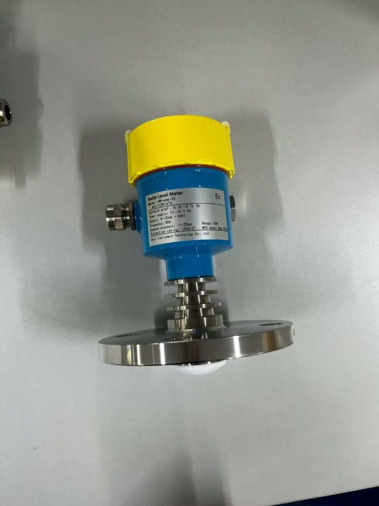
Radar level measurement is based on transmitting electromagnetic waves toward the product surface and receiving the reflected signals.
The instrument determines the distance between the antenna and the product surface by analyzing the signal’s travel time or frequency difference, depending on the radar technology.
The relationship between frequency and wavelength is:
Wavelength = Speed of light / Frequency
As frequency increases, wavelength decreases.
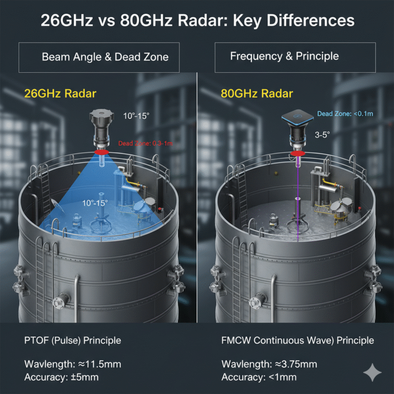
For an antenna with a comparable effective aperture, a shorter wavelength generally allows a narrower beam angle.
Here is a simplified comparison:
| Radar Frequency | Approximate Wavelength | Typical Beam Characteristics |
|---|---|---|
| 6 GHz | 50 mm | Relatively wide |
| 26 GHz | 11.5 mm | Approximately 8°-10° for some antennas |
| 80 GHz | 3.75 mm | Approximately 3° for selected antennas |
Actual beam angles depend on antenna diameter, antenna design, and the manufacturer’s specifications. These figures are illustrative rather than universal values.
What Does a 3° Beam Angle Mean?
The main advantage of a narrow radar beam is that more of the transmitted energy is concentrated within a smaller angular area.
This helps reduce reflections from internal tank structures, such as:
- Heating coils
- Ladders and support structures
- Internal pipes
- Reinforcement beams
- Agitator shafts
- Tank walls
For example, an 80 GHz radar with a 3° beam angle can generally provide better clearance from nearby obstacles than a radar with a much wider beam angle, provided that the instrument is correctly positioned.
How to Calculate the Radar Beam Diameter
The approximate beam diameter at a given distance can be calculated using:
Beam diameter = 2 x Distance x tan(Beam angle / 2)
For a radar transmitter with a 3° beam angle:
| Distance to Product Surface | 3° Beam | 10° Beam | 21° Beam |
|---|---|---|---|
| 10 m | 0.52 m | 1.75 m | 3.71 m |
| 20 m | 1.05 m | 3.50 m | 7.40 m |
These values represent the nominal geometric beam diameter based on the specified beam angle. Actual radar radiation patterns may include side lobes, and reflections outside the nominal beam may still affect measurement performance.
Why is this important?
Imagine a storage tank containing several internal heating pipes and support structures.
A wide-angle radar may receive unwanted reflections from these objects, making it more difficult to identify the actual product surface.
A narrow-beam 80 GHz radar reduces the area illuminated by the main beam and therefore helps minimize interference.
This is one of the most important reasons why 80 GHz radar is widely used in modern storage tanks, process vessels, and applications with limited installation space.
2. Comparison of Three Major Radar Level Transmitter Options
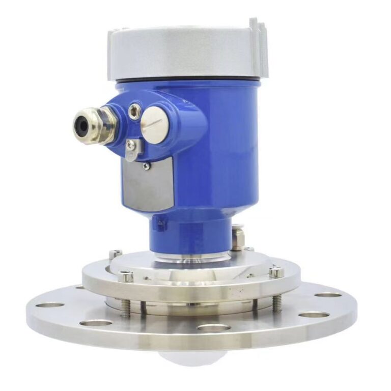
Different manufacturers offer radar level transmitters with different antenna designs, measurement technologies, and performance specifications.
The following comparison provides an overview of three representative product families.
| Parameter | E+H Micropilot NMR81 | VEGA VEGAPULS 6X | TianKang TKWL-1400 |
|---|---|---|---|
| Frequency | 80 GHz version | 6 / 26 / 80 GHz options | 76-81 GHz |
| Technology | FMCW radar | FMCW radar | FMCW radar |
| Accuracy | Up to 0.5 mm, depending on configuration | Up to ±1 mm, depending on configuration | Millimeter-level, according to manufacturer specifications |
| Maximum measuring range | Up to 70 m, depending on configuration | Up to 120 m, depending on configuration | Up to 120 m, depending on configuration |
| Process temperature | Configuration-dependent | Configuration-dependent | Configuration-dependent |
| Process pressure | Configuration-dependent | Configuration-dependent | Configuration-dependent |
| Beam angle | Approximately 3° for the relevant antenna | Depending on antenna configuration | Depending on antenna configuration |
Important: The values above are indicative product-family information, not a guarantee that all listed specifications are available simultaneously. Actual limits must be confirmed against the latest manufacturer datasheet for the selected antenna, process connection, and instrument configuration.
How Should You Choose?
For high-accuracy tank gauging:
E+H Micropilot NMR81 is worth considering when measurement accuracy, tank gauging requirements, and relevant metrological approvals are important.
For demanding process applications:
VEGA VEGAPULS 6X offers different frequency and antenna configurations. It is worth evaluating when process conditions, temperature, pressure, and measuring range are particularly demanding.
For conventional industrial storage tanks:
Suitable domestic 80 GHz radar transmitters can provide a competitive solution for general liquid and solid level measurement, provided that their actual performance and application limits meet the project requirements.
Do not select a radar transmitter based on frequency or accuracy alone.
Always check the measuring range, antenna type, process temperature, pressure rating, dielectric properties, and installation conditions.
3. Four Applications Where 80 GHz Radar Requires Careful Evaluation
Although 80 GHz radar has many advantages, it is not suitable for every application.
The following four conditions deserve particular attention.
3.1 Thick Foam on the Product Surface
Some applications, such as fermentation tanks, wastewater treatment processes, and certain chemical production systems, may generate thick foam.
Foam can absorb or scatter part of the transmitted microwave energy, weakening the reflected signal from the actual liquid surface.
Possible symptoms include:
- Unstable level readings
- Intermittent signal loss
- Incorrect surface detection
- Large measurement fluctuations
Depending on the foam properties and process conditions, guided wave radar or another measurement technology may be a better choice.
However, the selection should be verified under actual operating conditions.
3.2 Liquids with Low Dielectric Constants
Radar measurement depends partly on the ability of the product surface to reflect electromagnetic waves.
Some light hydrocarbons, solvents, and other low-dielectric liquids produce relatively weak reflections.
As a result, the received signal may be less stable.
For these applications, guided wave radar can be considered as an alternative, particularly when a stable probe reflection can be established.
The dielectric constant is an important selection parameter, but it should not be used as the only decision criterion.
Tank geometry, measuring distance, antenna design, and surface conditions must also be considered.
3.3 Long-Range Measurement in Dusty Solid Silos
80 GHz radar is also used for measuring powders, granules, cement, biomass, and other bulk solids.
Its narrow beam can help reduce interference from silo walls and internal structures.
However, long measuring distances combined with heavy dust concentrations may weaken the received signal.
For these applications, engineers should evaluate:
- Maximum measuring distance
- Dust concentration
- Antenna design
- Silo geometry
- Filling and discharge conditions
- Availability of air-purge connections
A suitable antenna and optional air-purge system may improve long-term measurement reliability.
3.4 Severe Material Build-Up or Crystallization
Some chemical products, viscous liquids, and crystallizing materials can accumulate on the antenna surface.
This is particularly important for lens antennas.
Material build-up may change the antenna’s electromagnetic characteristics and weaken the transmitted or received signal.
For such applications, consider:
- Antennas with suitable non-stick surfaces
- Air-purge connections
- Appropriate antenna materials
- Installation positions that minimize product accumulation
If severe build-up cannot be avoided, guided wave radar or another contact measurement technology may be more appropriate.
The key point: 80 GHz radar provides a narrow beam, a small measuring dead zone in suitable configurations, and high measurement resolution. However, it is not a universal solution for every process condition.
4. Correct Installation Is More Important Than Specifications Alone
Even an advanced radar level transmitter can produce unreliable readings if it is installed incorrectly.
The following installation considerations are particularly important.
4.1 Keep the Main Radar Beam Clear
Avoid placing the radar antenna where the main beam directly intersects:
- Internal support beams
- Ladders
- Heating coils
- Filling pipes
- Agitator structures
- Other metallic obstructions
Remember that the radar beam forms a three-dimensional cone, not simply a straight vertical line.
The installation position should be evaluated using the actual antenna beam angle and the distance to the product surface.
4.2 Maintain Sufficient Clearance from the Tank Wall
If the antenna is installed too close to the tank wall, reflections from the wall may interfere with the measurement.
The required clearance depends on the antenna design, tank diameter, measuring range, and internal structures.
Some manufacturers specify minimum distances of approximately 200 mm or more for particular models.
In practice, larger clearances may be required in large tanks or installations with significant internal obstructions.
Always follow the manufacturer’s installation instructions rather than applying one fixed distance to every radar transmitter.
4.3 Avoid Installing the Radar at the Tank Center Without Verification
For many cylindrical tanks, installing the radar directly at the center may increase the risk of unwanted reflections from the tank bottom, internal structures, or other reflective surfaces.
An offset position may be preferable, depending on tank geometry and the manufacturer’s recommendations.
There is no universal offset ratio suitable for every tank.
The final position should be selected according to the antenna characteristics, tank structure, and installation drawings.
4.4 Pay Attention to the Mounting Nozzle
A long mounting nozzle can behave like a short waveguide and introduce additional reflections.
This may create false echoes or increase the effective dead zone.
To avoid these problems:
- Keep the mounting nozzle as short as practical.
- Select a nozzle diameter compatible with the antenna.
- Avoid internal protrusions and sharp obstructions.
- Follow the manufacturer’s recommendations for antenna positioning.
- Check whether the antenna should extend beyond the nozzle.
4.5 Perform False Echo Mapping Under Real Operating Conditions
This is one of the most frequently overlooked commissioning procedures.
Many radar transmitters provide a false echo suppression or mapping function.
The instrument records unwanted reflections from fixed tank structures and distinguishes them from the actual product surface.
However, incorrect mapping can create serious problems.
Consider a tank equipped with an agitator.
When the agitator is stopped, the radar may receive a relatively stable echo pattern.
Once the agitator starts, the moving blades and changing surface conditions may produce additional reflections.
If false echo mapping is performed only when the tank is empty and the agitator is stopped, these operating conditions may not be properly represented.
An even more serious problem occurs when the actual product surface echo is mistakenly included in the suppression curve.
The instrument may then ignore the real level signal.
Recommended commissioning procedure:
- Confirm the correct tank height and measuring reference.
- Check the antenna position and mounting geometry.
- Evaluate the radar signal under representative operating conditions.
- Perform false echo mapping according to the manufacturer’s procedure.
- Verify the results at several known or independently measured liquid levels.
- Repeat the checks under different operating conditions, including agitator operation where applicable.
Never assume that one empty-tank mapping operation is sufficient for every application.
5. What Should Be Checked During Acceptance? Understanding JJG 971-2019
For projects in China, JJG 971-2019, Verification Regulation of Level Meters, provides an important reference for liquid level instrument verification.
The regulation covers initial verification, subsequent verification, and in-service inspection.
It includes reflective instruments such as radar level meters, ultrasonic level meters, and guided wave radar level meters.
The following points are particularly useful when discussing measurement performance and acceptance.
5.1 Clearly Define the Maximum Permissible Error
The regulation provides different ways of expressing maximum permissible error, including percentage of full scale and absolute error.
For example:
- ±0.1% FS
- ±0.5% FS
- ±1 mm
- ±2 mm
These specifications are not interchangeable.
A statement such as “accuracy ±1 mm” should be accompanied by the applicable measuring conditions and instrument specifications.
Before signing a technical agreement, confirm whether the specified accuracy refers to the complete measuring range, a particular measuring condition, or a specific verification procedure.
5.2 Check Display Resolution
Display resolution and measurement accuracy are two different concepts.
A transmitter may have a high-resolution display without achieving the same level of measurement accuracy.
According to JJG 971-2019, the digital display resolution should meet the requirements specified in the regulation relative to the maximum permissible error.
Therefore, engineers should check both the specified accuracy and the actual display resolution.
5.3 Verify the Accuracy of the Reference Equipment
When checking a radar level transmitter, the reference instrument or verification equipment must have sufficient measurement capability.
JJG 971-2019 specifies requirements for the expanded uncertainty of the verification standard relative to the maximum permissible error.
If the reference equipment is not sufficiently accurate, the verification result may not be reliable.
This is particularly important when evaluating instruments with millimeter-level accuracy claims.
5.4 Check Vertical Alignment
The regulation specifies a vertical deviation limit of no more than 1° for the relevant verification setup.
This requirement should not automatically be treated as a universal field installation specification.
For actual tank installations, engineers should also follow the manufacturer’s requirements for antenna alignment and mounting geometry.
An incorrectly aligned radar may direct its main beam toward internal structures or reflective surfaces, resulting in unstable readings.
5.5 Keep Verification Records Up to Date
JJG 971-2019 provides guidance on verification intervals, generally not exceeding one year under the applicable requirements.
For instruments used in important measurement applications, maintenance and verification records should be properly maintained.
Important: JJG 971-2019 is a metrological verification reference. It should not be confused with a universal installation standard or a substitute for the manufacturer’s product-specific instructions. The applicable clauses and requirements should be checked against the official regulation and the actual verification scope.
6. Practical Troubleshooting: Why Does the Radar Reading Differ by 30 mm?
Consider the following situation.
A newly installed 80 GHz radar level transmitter has a nominal accuracy specification of ±1 mm.
After commissioning, its reading differs from manual tank gauging by approximately 30 mm.
Furthermore, the deviation becomes larger as the liquid level increases.
What should engineers investigate first?
A 30 mm deviation may be significant in a storage tank, particularly when the measurement is used for inventory management, process control, or commercial accounting.
The potential volume difference should be calculated using the actual tank geometry and certified tank capacity table.
Before replacing the transmitter, follow a systematic troubleshooting procedure.
Step 1: Check the Reference Measurement
First, confirm whether the manual measurement is reliable.
Check:
- Is the manual measuring tape calibrated?
- Is the same reference datum being used?
- Is the tank reference height correctly defined?
- Is the tank capacity table applicable?
- Are both measurements taken under comparable operating conditions?
Sometimes, an apparent instrument error is actually caused by inconsistent reference measurements.
Step 2: Check the Installation Geometry
Inspect the radar mounting position.
Pay attention to:
- Antenna alignment
- Flange installation
- Mounting nozzle length
- Distance from the tank wall
- Nearby internal structures
- Tank deformation or inclination
If the radar is not properly aligned, its beam may be directed toward unwanted reflective surfaces.
Step 3: Check Instrument Configuration
Review the configuration parameters:
- Tank height
- Upper and lower measuring limits
- Blocking distance
- Distance offset
- Reference point
- Output scaling
An incorrect reference point or offset can create a systematic measurement difference.
Step 4: Recheck False Echo Suppression
If the false echo curve was created incorrectly, the radar may identify part of the actual product surface signal as interference.
Repeat the procedure according to the manufacturer’s instructions and verify the measurement at several different levels.
Suggested verification points include:
- 0%
- 25%
- 50%
- 75%
Where practical, compare the transmitter reading with an independent reference measurement at each point.
Step 5: Arrange Formal Verification if Necessary
Only after the reference measurement, installation geometry, configuration, and signal processing have been checked should the instrument be sent for formal verification or further technical inspection.
This approach helps avoid unnecessary instrument replacement and identifies the actual cause of the deviation.
Conclusion: Understand the Application Before Choosing 80 GHz Radar
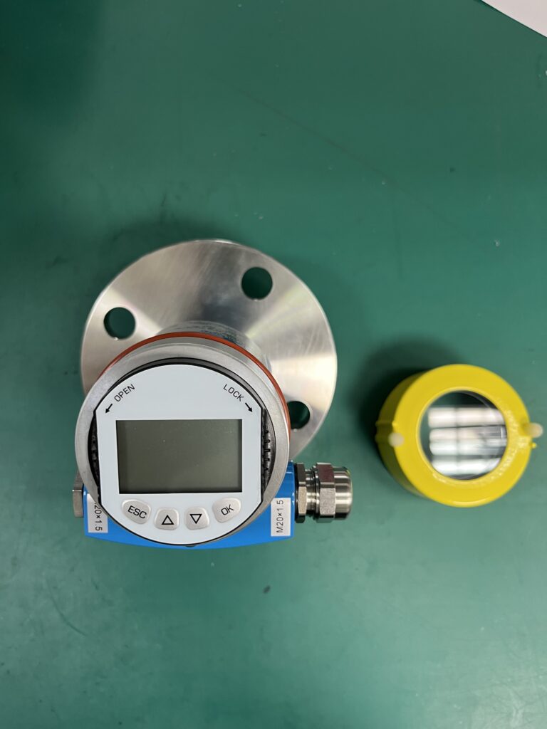
80 GHz radar level transmitters offer important advantages for modern industrial measurement.
Their short wavelength and narrow beam angle can help reduce interference from tank structures, improve measurement reliability, and support applications where installation space is limited.
However, frequency alone does not determine measurement performance.
The actual result depends on several factors:
- Antenna design and beam angle
- Dielectric properties of the medium
- Tank geometry
- Foam, dust, and material build-up
- Mounting position and nozzle design
- False echo mapping and commissioning
- Correct instrument configuration
A radar transmitter with a nominal accuracy of ±1 mm cannot guarantee ±1 mm performance if it is installed incorrectly or configured under unsuitable operating conditions.
Remember: Select the right radar for the application, install it correctly, and verify its performance under real operating conditions.
That is how an 80 GHz radar level transmitter delivers reliable measurement in industrial applications.