
From impulse lines to primary elements: a practical maintenance checklist for reliable flow measurement.
Differential pressure (DP) flowmeters are widely used in industrial applications because of their simple construction, proven reliability, and lack of moving parts. Many engineers consider them rugged instruments that require little maintenance.
However, field experience often tells a different story.
In many cases, the transmitter itself is not the main source of measurement problems. Instead, the actual trouble comes from seemingly insignificant components such as impulse lines, condensate pots, valve manifolds, and pressure connections.
A partially blocked impulse line, an unbalanced condensate pot, or an incorrect three-valve manifold operating sequence can introduce measurement errors that remain unnoticed for months.
By the time the discrepancy appears in production reports or material balance calculations, the measurement error may have already affected process control and accounting.
This article provides a practical maintenance guide covering routine inspection, impulse line maintenance, primary element inspection, transmitter verification, troubleshooting, and maintenance records.
1. Understand the Entire Measurement System Before Maintenance

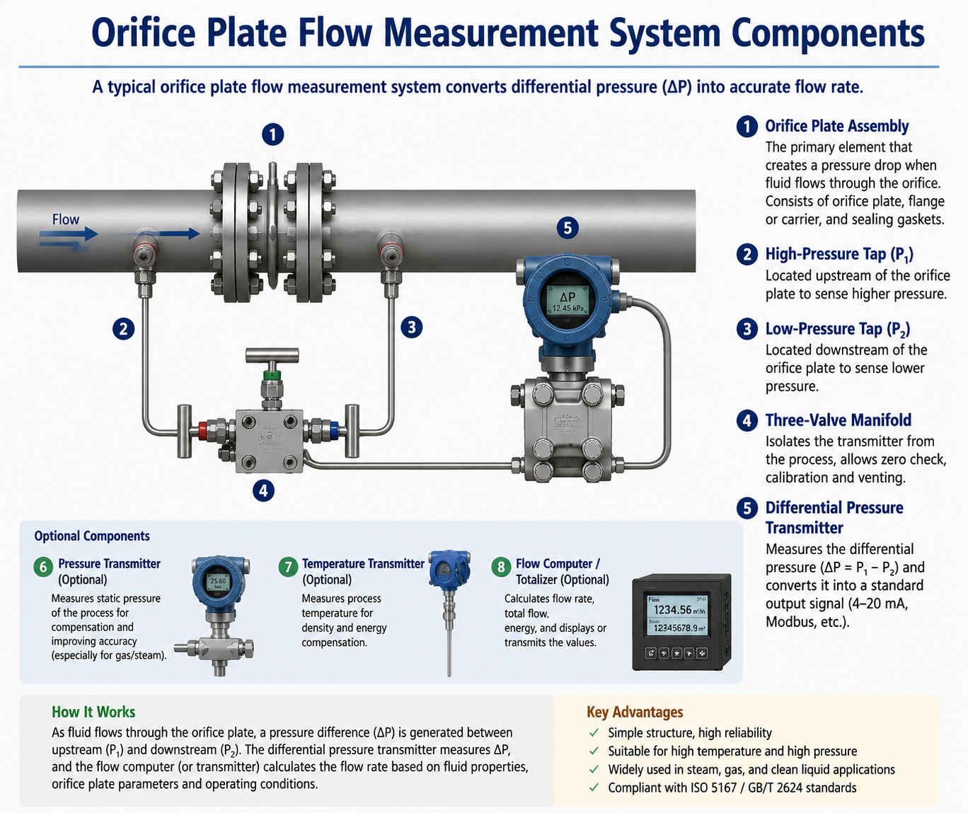
A differential pressure flowmeter is not simply a transmitter. It is a complete measurement system consisting of several interconnected components.
The measurement process generally follows this sequence:
Primary element → Impulse lines → Valve manifold → DP transmitter → Flow computer or DCS
Each component plays an important role. A problem in any part of the system can affect the final flow measurement.
The main components include:
- Primary element: Orifice plates, flow nozzles, Venturi tubes, and other restriction devices generate a differential pressure related to flow rate.
- Impulse lines: These transmit the upstream and downstream pressures from the primary element to the transmitter.
- Valve manifold: Three-valve or five-valve manifolds provide pressure isolation, equalization, and instrument protection.
- DP transmitter: Converts the measured differential pressure into an electrical signal, typically 4–20 mA.
- Secondary instrumentation: Flow computers, totalizers, or DCS systems calculate flow rate using the configured measurement parameters.
During troubleshooting, follow the signal path instead of immediately replacing the transmitter. This approach can save considerable maintenance time.
2. Routine Inspection: Five Things to Check Every Week
The purpose of routine inspection is not necessarily to repair equipment but to identify abnormal conditions before they develop into serious failures.
A weekly inspection is a useful starting point for normal operating conditions. For dirty, corrosive, crystallizing, or low-temperature applications, inspection frequency should be increased according to actual operating conditions.
Pay attention to the following five areas.
1. Check for leakage
Inspect flange connections, root valves, impulse line fittings, valve stems, and drain connections.
Look for liquid leakage, crystallization, corrosion, or other visible signs of pressure loss.
2. Check instrument readings
When the process is at a confirmed no-flow condition, check whether the differential pressure approaches the expected zero value.
During normal operation, compare the readings with process expectations and other available measurement references.
3. Inspect impulse lines
Check insulation and heat tracing.
Look for liquid accumulation, freezing, blockage, abnormal heating, mechanical damage, or deformation.
4. Check accessories
For steam applications, verify that condensate pots are installed correctly and that the liquid levels on both sides are properly balanced.
For seal-fluid applications, inspect the condition and level of the sealing liquid where applicable.
5. Check the installation environment
Inspect transmitter wiring, grounding, enclosure sealing, and cable entries.
Avoid excessive vibration, high ambient temperatures, and corrosive environmental conditions.
3. Impulse Lines and Valve Manifolds: Common Sources of Measurement Problems

Impulse lines are particularly important because differential pressure signals are often relatively small, ranging from a few kilopascals to several tens of kilopascals.
Even minor disturbances can affect the measurement.
Common causes include:
- Solid particles accumulating inside impulse lines.
- Crystallization or sediment buildup.
- Condensate accumulation.
- Gas bubbles in liquid measurement applications.
- Unequal liquid levels between the high-pressure and low-pressure sides.
- Leakage or partial blockage in pressure connections.
The basic maintenance principle is to maintain symmetrical and unrestricted pressure transmission on both sides.
3.1 Periodic Draining and Cleaning
The inspection and draining frequency depends on the process medium.
For relatively clean media, monthly inspection may be sufficient. For dirty, crystallizing, or particle-containing media, weekly or even per-shift inspection may be necessary.
During maintenance:
- Confirm that the process conditions allow draining and that the required isolation procedure is available.
- Isolate the instrument or switch to an approved bypass arrangement according to the site procedure.
- Drain the high-pressure and low-pressure impulse lines separately.
- Observe the discharged medium for sediment, crystallization, discoloration, or abnormal contamination.
- Compare the discharge conditions on both sides.
- Restore the system according to the manufacturer’s recommended operating sequence.
For steam applications, allow the condensate pots to reach stable and balanced liquid levels before returning the transmitter to normal operation.
Do not use ordinary metal wire to forcefully clean pressure tapping holes. This may damage the sharp edge or geometry of the primary element and affect measurement accuracy.
3.2 Installation Position Matters
The correct transmitter installation position depends on the measured medium.
Liquid measurement:
The transmitter is generally installed below the pressure tapping points so that trapped gas can return toward the process line.
Gas measurement:
The transmitter is generally installed above the pressure tapping points to allow condensate to drain back toward the process line.
Steam measurement:
Condensate pots are normally used to establish consistent liquid columns on both sides of the transmitter.
Incorrect installation elevation can introduce additional hydrostatic head and cause zero-point deviation. The effect should be calculated and compensated according to the actual installation conditions.
Straight pipe requirements must also be considered.
For orifice plate installations, the required upstream and downstream straight lengths depend on the applicable standard, pipe diameter, beta ratio, and upstream disturbance configuration.
Refer to GB/T 2624 or ISO 5167 and the relevant installation requirements rather than applying one fixed straight-pipe length to every application.
3.3 Correct Three-Valve Manifold Operating Sequence
This is one of the most important maintenance operations for differential pressure transmitters.
A typical three-valve manifold consists of:
- High-pressure valve (H)
- Low-pressure valve (L)
- Equalizing valve (B)
The equalizing valve connects the high-pressure and low-pressure chambers, allowing pressure to be balanced across the transmitter sensing element.
Incorrect operation can expose the diaphragm to excessive differential pressure or cause measurement errors.
Common commissioning sequence
The following is a commonly used operating sequence for a conventional three-valve manifold. Always follow the transmitter manufacturer’s instructions and site-specific procedures.
Initial condition:
- High-pressure valve H: Closed
- Low-pressure valve L: Closed
- Equalizing valve B: Open
Operating procedure:
- Keep the equalizing valve B open.
- Slowly open the low-pressure valve L.
- Slowly open the high-pressure valve H.
- Allow pressure to stabilize on both sides.
- Check for leakage and abnormal conditions.
- Close the equalizing valve B to establish normal differential pressure measurement.
Operating reminder:
Open equalizing valve → Open low-pressure valve → Open high-pressure valve → Close equalizing valve.
Common shutdown sequence
For a typical isolation procedure:
- Open the equalizing valve B to balance pressure across the transmitter.
- Close the low-pressure valve L.
- Close the high-pressure valve H.
- If maintenance or removal is required, release the trapped pressure through the designated vent or drain connections after confirming safe isolation.
Shutdown reminder:
Open equalizing valve → Close low-pressure valve → Close high-pressure valve.
The exact sequence may vary depending on manifold design, process medium, pressure conditions, and manufacturer instructions. Special precautions are necessary for steam, toxic, corrosive, and seal-fluid applications.
3.4 Two Common Hidden Problems
Problem 1: Internal leakage through the equalizing valve
If the equalizing valve does not seal properly during normal measurement, the high-pressure and low-pressure sides may partially communicate.
This can reduce the measured differential pressure and cause the indicated flow rate to become lower than the actual value.
To investigate:
- Confirm that the high-pressure and low-pressure root valves are properly isolated.
- Open the equalizing valve and allow the pressure to stabilize.
- Check the transmitter output under the confirmed equal-pressure condition.
- If an unexpected offset remains, investigate zero-point deviation, residual pressure, valve leakage, and possible sensing element damage.
A separate isolation and pressure-holding test should be used when checking the equalizing valve’s sealing performance.
Problem 2: Incorrect valve operation
Leaving valves in an incorrect configuration can cause pressure imbalance or unwanted communication between the two sides.
For steam and seal-fluid applications, improper operation may also disturb condensate or sealing liquid levels.
Always verify the final valve positions before returning the instrument to service.
4. Primary Element Inspection: Four Areas to Check
The primary element directly affects the differential pressure-flow relationship.
For a standard orifice plate, its geometry and dimensions are essential to the flow calculation. The associated calculation sheet should be retained as an important technical reference.
Inspection is recommended during scheduled plant shutdowns or when operating conditions indicate possible wear, corrosion, or blockage.
Pay attention to four areas.
1. Sharp-edge condition
The upstream edge of a standard orifice plate should remain sharp and free from damage.
Check for:
- Rounded edges.
- Mechanical damage.
- Erosion.
- Notches or deformation.
Wear can change the effective opening and discharge coefficient, resulting in measurement deviation.
2. Plate flatness
Check whether the plate has become distorted.
Deformation of the upstream or downstream surface can affect the flow characteristics.
A severely deformed plate should be replaced rather than simply hammered back into shape.
3. Scaling and corrosion
Inspect both surfaces and the orifice opening for deposits, corrosion pits, and accumulated solids.
After cleaning, verify the relevant dimensions before reinstalling the plate.
Particle-containing and corrosive applications require particular attention.
4. Installation details
Verify the following:
- The plate is installed in the correct flow direction.
- The sharp edge faces upstream.
- The gasket does not protrude into the pipe.
- The pressure tapping connections are not obstructed.
- The plate identification and calculation data match the installation.
Incorrect installation can significantly affect measurement performance.
5. Transmitter Zero Check: Zero Adjustment Is Not Always the Solution

Zero verification is an important part of differential pressure transmitter maintenance.
However, zero adjustment should never be performed before confirming the actual pressure conditions.
A recommended checking procedure is:
- Confirm that the process is in a suitable no-flow condition.
- Isolate the high-pressure and low-pressure sides according to the approved procedure.
- Open the equalizing valve to balance pressure across the transmitter.
- Allow sufficient time for pressure stabilization.
- Check whether the output corresponds to the expected zero differential pressure.
- If the deviation exceeds the allowable tolerance, perform zero adjustment according to the manufacturer’s instructions.
For a typical 4–20 mA transmitter configured for zero differential pressure at 4 mA, the output should be approximately 4 mA under the correct equal-pressure condition.
However, several factors must be considered.
Zero elevation and suppression
Remote diaphragm seals, filled capillaries, seal fluids, and differences in installation elevation may introduce a designed hydrostatic pressure offset.
This is sometimes intentional and must not be removed by blindly resetting the transmitter to zero.
Range configuration
If the measurement trend is stable but the displayed flow rate has a consistent proportional error, check:
- Transmitter LRV and URV settings.
- Configured differential pressure range.
- DCS or flow computer scaling.
- Calculation sheet parameters.
- Fluid density and compensation settings.
Signal fluctuations
If the transmitter output fluctuates, investigate the external causes first:
- Gas bubbles in liquid measurement.
- Two-phase flow.
- Partially blocked impulse lines.
- Process valve disturbances.
- Mechanical vibration.
Only after these factors have been investigated should damping adjustments be considered.
A damping value of approximately 0.5–2 seconds may be suitable for some applications, but the final setting must match process dynamics and control requirements.
Suggested verification schedule
- Quarterly: Online zero verification where operating conditions permit.
- Every 6–12 months: Full-range performance verification using a suitable calibrated pressure source, depending on application criticality and maintenance policy.
6. Quick Troubleshooting Guide
The following table summarizes common symptoms and recommended initial checks.
| Symptom | Possible Cause | Recommended Check |
|---|---|---|
| Flow reading gradually decreases | High-pressure impulse line blockage or leakage | Inspect and compare the high-pressure side |
| Flow reading becomes unusually high | Low-pressure side blockage or incorrect orifice plate installation | Inspect low-pressure line and flow direction |
| Severe signal fluctuation | Two-phase flow, gas bubbles, or insufficient straight pipe length | Check process conditions, venting, and installation |
| Constant measurement offset | Unequal condensate levels or transmitter zero deviation | Check condensate pots and verify zero |
| Differential pressure cannot return to zero | Equalizing valve problem or transmitter sensing element damage | Check pressure equalization and perform transmitter verification |
| Flow reading is consistently proportional to actual flow | Incorrect transmitter range or DCS scaling | Compare configuration with the calculation sheet |
A practical troubleshooting principle is to follow this order:
Power and wiring → Impulse lines → Valve manifold → Primary element → Process conditions → Transmitter configuration.
Avoid unnecessary transmitter disassembly. Every unnecessary intervention creates another opportunity to introduce measurement errors.
7. Maintenance Intervals and Record Keeping
Effective maintenance requires a defined schedule and reliable records.
For instruments subject to mandatory metrological verification, the verification interval must comply with applicable regulations and the requirements of the relevant authority.
For other applications, maintenance and calibration intervals should be determined according to process conditions, instrument performance, measurement criticality, and the plant’s maintenance policy.
A practical maintenance schedule may include:
Weekly to Monthly
- Routine visual inspection.
- Leakage checks.
- Impulse line inspection and draining where necessary.
- Winter heat-tracing and insulation checks.
Quarterly to Semiannually
- Online zero verification where possible.
- Impulse line sealing inspection.
- Condensate pot and valve manifold inspection.
- Review of abnormal measurement trends.
Annually
- Transmitter zero and range verification.
- Flow computer and DCS parameter comparison.
- Review of installation conditions and process changes.
During Major Overhauls or According to Condition
- Remove and inspect the orifice plate.
- Check sharp-edge condition and dimensions.
- Inspect for erosion, corrosion, and deformation.
- Verify the primary element against its calculation data.
- Perform the required metrological verification.
A maintenance record should contain at least:
- Instrument identification and installation date.
- Primary element specifications and calculation sheet number.
- Transmitter model and measurement range.
- Verification date and results.
- Dates and details of cleaning, draining, and maintenance.
- Abnormal readings and corrective actions.
- Replacement parts and configuration changes.
Good maintenance records support reliability management, troubleshooting, and measurement traceability. They are also valuable when measurement discrepancies arise between production departments or during commercial accounting.
8. Seasonal Maintenance and Safety Precautions
Environmental conditions can significantly affect differential pressure measurement systems.
Winter: Prevent Freezing
Impulse lines, condensate pots, and valve manifolds should be properly insulated and heat-traced where required.
Regularly verify that heat tracing is operating correctly.
Freezing can block impulse lines, distort pressure transmission, and potentially damage the transmitter sensing system.
Summer: Control Ambient Temperature
Check the transmitter’s ambient temperature against its specified operating limits.
Avoid prolonged exposure to excessive heat and ensure that the installation environment provides adequate thermal protection.
Pressure Safety: Never Ignore Isolation and Depressurization
Before draining, cleaning, or removing any component:
- Confirm process isolation.
- Verify that pressure has been safely released.
- Use suitable collection equipment.
- Follow the site’s permit-to-work and safety procedures.
Never loosen pressure fittings under pressure.
Steam, toxic, corrosive, and high-temperature media require additional precautions.
Hazardous Areas: Maintain Explosion Protection
Before opening an instrument enclosure or performing electrical maintenance in a hazardous area, confirm that the required electrical work authorization and isolation procedures are in place.
Check grounding connections, cable glands, and explosion-proof conduit fittings.
Maintain the equipment’s certified protection integrity.
9. Final Thoughts: Three Principles for Reliable DP Flow Measurement
Differential pressure flowmeters are proven instruments, but their long-term accuracy depends on more than the transmitter itself.
Three basic principles should guide maintenance activities.
1. Installation Is the Foundation
Correct straight pipe lengths, pressure tapping positions, impulse line routing, and transmitter elevation are essential for reliable measurement.
2. Operation Is the Key
Correct valve manifold operation protects the transmitter sensing element from unnecessary differential pressure and pressure shocks.
3. Maintenance Is the Guarantee
Regular inspection, proper impulse line cleaning, primary element checks, transmitter verification, and complete maintenance records help maintain measurement reliability over time.
The most important lesson is simple:
A robust flowmeter does not mean a maintenance-free flow measurement system.
In many industrial applications, the smallest components deserve the greatest attention.
Note: This article provides general maintenance guidance. Actual operating procedures, inspection intervals, and verification requirements must follow the instrument manufacturer’s documentation, site-specific safety procedures, and applicable local metrological regulations.
About Zero Instrument
Zero Instrument provides industrial flow measurement solutions, including differential pressure transmitters, orifice plate flowmeters, electromagnetic flowmeters, vortex flowmeters, and other process instrumentation for industrial applications.
For technical assistance or flow measurement inquiries, please contact our engineering and sales team.