
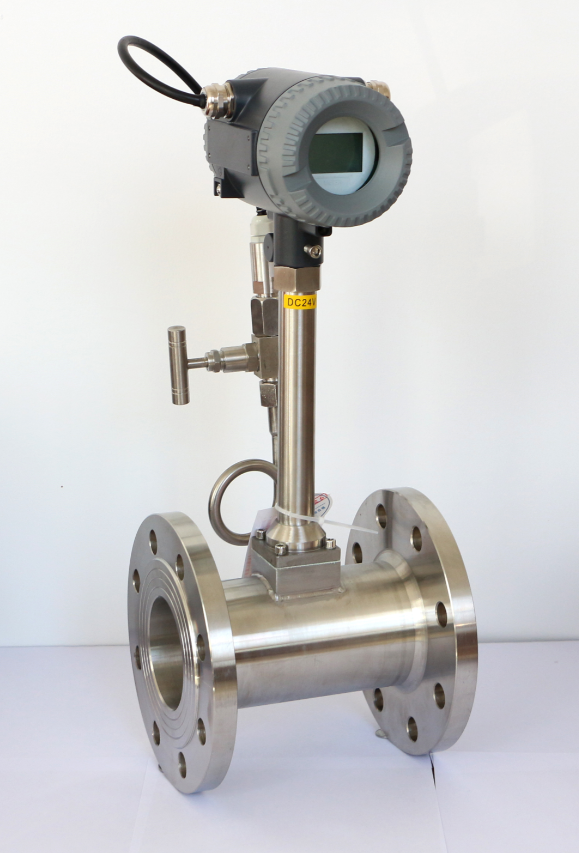
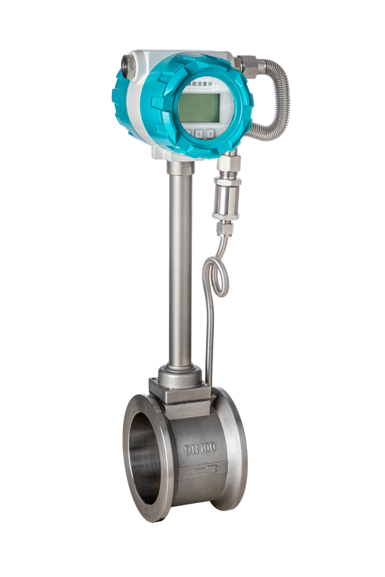
Vortex flow meters are widely used in industrial applications because of their simple construction, absence of moving parts, relatively low maintenance requirements, and ability to measure liquids, gases, and steam.
However, one common challenge occurs when a vortex flow meter is installed too close to a pump or another source of mechanical vibration.
Under these conditions, operators may experience unstable flow readings, sudden signal spikes, false flow indications, inaccurate totalization, or frequent flow alarms in the distributed control system (DCS).
In many cases, the flow meter itself is not defective. Instead, the measurement instability results from a combination of mechanical vibration, fluid pulsation, flow disturbances, and unsuitable installation conditions.
This article explains why these problems occur, how to identify the actual cause, and which corrective measures can improve vortex flow measurement reliability.
1. Common Symptoms of Vortex Flow Meter Instability
When a vortex flow meter operates near a vibrating pump, several symptoms may appear.
1.1 Sudden Flow Reading Fluctuations
The instantaneous flow reading may change rapidly even when the process operating conditions appear stable.
Common observations include:
- Large flow fluctuations during pump startup or shutdown.
- Unstable readings when the pump speed changes.
- Sudden spikes in the DCS flow trend.
- Unexpectedly high or low flow indications.
- Fluctuations that become more severe as pump operating conditions change.
These symptoms can indicate interference, but they do not prove that mechanical vibration is the only cause.
1.2 False Flow Indications
In some installations, the flow meter may indicate flow even when no actual fluid movement is expected.
Possible causes include mechanical vibration being interpreted as a vortex signal, electrical interference, or incorrect signal-processing settings.
However, operators should first confirm that the pipeline is actually at zero flow. Leakage, backflow, valve bypassing, and fluid movement during shutdown can also produce measurable flow.
1.3 Unstable Totalized Flow
If the instantaneous flow signal contains significant disturbances, the accumulated flow measurement may also become inaccurate.
This can affect:
- Process monitoring.
- Production reporting.
- Energy consumption calculations.
- Water and utility management.
- Material balance calculations.
For applications involving billing or custody transfer, persistent measurement instability requires particular attention.
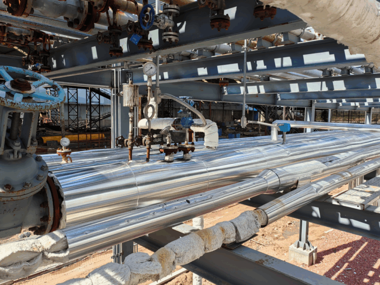
1.4 Visible Pipeline Vibration
In severe cases, vibration may be noticeable along the pipework or around the flow meter installation.
Possible indications include:
- Excessive lateral pipe movement.
- Vibrating pipe supports.
- Unusual mechanical noise.
- Loose or damaged mounting components.
- Repeated movement near pump connections.
Visible vibration should be treated as a warning sign requiring investigation, rather than as a quantitative measurement of vibration severity.
2. Why Does Pump Vibration Affect Vortex Flow Measurement?
2.1 Understanding the Vortex Shedding Principle
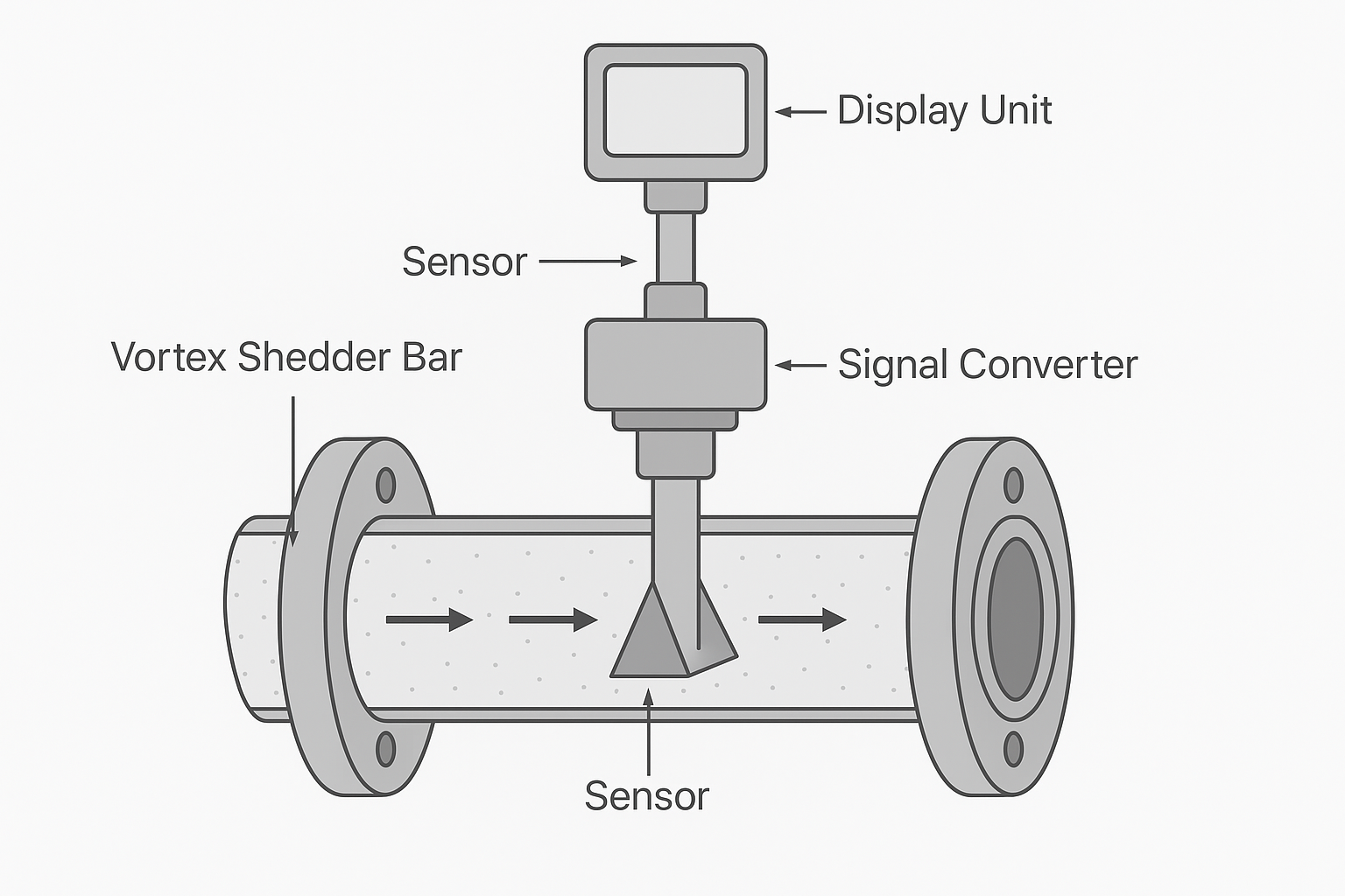
A vortex flow meter operates according to the vortex shedding principle.
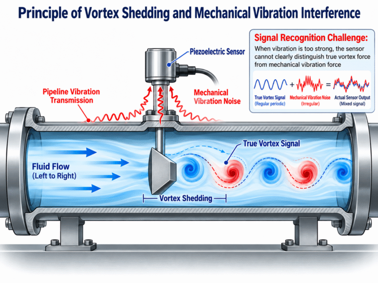
When fluid passes a bluff body installed inside the measuring tube, alternating vortices form downstream.
This phenomenon is commonly known as the Kármán vortex street.
Within the specified operating range, the vortex shedding frequency is approximately proportional to the average fluid velocity.
The relationship can be expressed as:
f = St × V / d
Where:
- f = vortex shedding frequency (Hz)
- St = Strouhal number
- V = average fluid velocity (m/s)
- d = characteristic width of the bluff body (m)
The instrument detects the vortex shedding frequency and converts it into a flow measurement.
Because the measurement depends on detecting relatively small periodic signals, unwanted mechanical disturbances may affect signal recognition.
2.2 Mechanical Vibration Transmitted Through the Pipeline
Pumps generate mechanical vibration during operation.
Potential sources include:
- Rotor imbalance.
- Shaft misalignment.
- Bearing wear or damage.
- Mechanical looseness.
- Hydraulic instability.
- Cavitation.
- Resonance in the pump or connected piping.
These vibrations can be transmitted through the pump casing, pipework, flanges, and supporting structures.
Many conventional vortex flow meters use piezoelectric sensing elements to detect the forces associated with vortex shedding.
Depending on sensor design, mechanical vibration can also be detected by the sensing system.
When the disturbance is sufficiently strong, the instrument may have difficulty separating the actual vortex shedding signal from vibration-related noise.
This may lead to unstable readings or false signal detection.
2.3 Interference Between Vibration Frequency and Vortex Frequency
Mechanical vibration becomes particularly problematic when its frequency components overlap with, or are otherwise difficult to distinguish from, the vortex shedding signal.
The resulting interference may affect the signal-processing system’s ability to identify the correct vortex frequency.
Possible consequences include:
- Incorrect vortex frequency recognition.
- Unstable pulse generation.
- Sudden changes in indicated flow.
- False flow detection.
- Reduced measurement repeatability.
The severity depends on the vibration frequency, amplitude, direction, sensor design, signal-processing technology, and actual flow conditions.
Not every vibration source will necessarily cause significant measurement error.
2.4 Fluid Pulsation from Pumps
Mechanical vibration is not the only source of measurement instability.
Pumps can also produce genuine pressure and flow pulsations.
This is especially important in systems using reciprocating or positive-displacement pumps.
Unlike mechanical vibration interference, fluid pulsation can cause actual changes in instantaneous flow velocity.
A vortex flow meter may therefore respond to real process fluctuations rather than simply generating false readings.
In centrifugal pump systems, hydraulic instability, cavitation, control valve operation, or unstable pump operating conditions may also contribute to fluctuating flow.
Important: Mechanical vibration and fluid pulsation require different corrective measures. Reducing vibration transmission does not necessarily eliminate hydraulic pulsation.
3. Installation Problems That Increase Measurement Instability
3.1 Installing the Flow Meter Too Close to the Pump
A flow meter installed immediately downstream of a pump may be exposed to several unfavorable conditions simultaneously:
- Mechanical vibration transmitted through the piping.
- Flow disturbances from nearby fittings.
- Pressure pulsation.
- Turbulence or unstable velocity profiles.
- Potential cavitation-related disturbances.
However, distance from the pump alone does not determine measurement performance.
A suitable installation must consider the complete piping arrangement, including straight pipe lengths, valve positions, supports, process conditions, and the manufacturer’s recommendations.
3.2 Insufficient Straight Pipe Length
Vortex flow meters generally require appropriate upstream and downstream straight pipe sections to establish acceptable measurement conditions.
The required lengths vary depending on:
- Flow meter manufacturer and model.
- Upstream elbows.
- Multiple elbows in different planes.
- Valves and partially open control valves.
- Pipe reducers and expanders.
- Other flow-disturbing components.
Some applications may require longer upstream straight runs than others.
A commonly encountered arrangement may specify an upstream straight length of approximately 20D and a downstream length of 5D, but these values should not be treated as universal installation requirements.
Here, D represents the nominal pipe diameter or the relevant internal diameter specified by the manufacturer.
Always consult the installation manual for the selected vortex flow meter.
3.3 Inadequate Pipeline Supports
Poorly supported piping may experience excessive movement or resonance during pump operation.
This can increase the vibration transmitted to the flow meter.
Common problems include:
- Long unsupported pipe spans.
- Damaged supports.
- Loose clamps.
- Incorrect support locations.
- Inadequate structural stiffness.
- Pipe resonance near pump excitation frequencies.
Proper pipe support design can significantly reduce some types of vibration-related problems.
However, support arrangements must also accommodate thermal expansion, pressure loads, and other piping design requirements.
3.4 Excessive Pipe Stress
Poor piping alignment or forced flange connections may introduce unwanted mechanical stress into the flow meter body.
This can result from:
- Incorrect flange alignment.
- Excessive installation force.
- Improper gasket installation.
- Thermal expansion.
- Inadequate support.
- Unsuitable piping layout.
A vortex flow meter should not be used to force misaligned piping into position.
4. How to Distinguish Mechanical Vibration from Actual Flow Pulsation
Before changing instrument settings or modifying the piping system, engineers should establish the most likely source of the unstable readings.
This step can prevent unnecessary instrument replacement and expensive piping modifications.
4.1 Compare Flow Trends with Pump Operating Conditions
Review the flow signal during:
- Pump startup.
- Steady-state operation.
- Pump speed changes.
- Control valve adjustments.
- Pump shutdown.
If the measurement instability changes significantly with pump speed, investigate whether the change is related to mechanical vibration, hydraulic pulsation, or a genuine change in flow.
Correlation alone does not identify the cause.
4.2 Measure Pipeline Vibration
Use suitable vibration measurement equipment to evaluate vibration at the flow meter and nearby piping.
Depending on the application, measurements may include:
- Vibration acceleration.
- Vibration velocity.
- Vibration displacement.
- Frequency spectrum.
- Vibration direction.
A frequency analysis can help identify vibration components associated with pump rotational speed, mechanical faults, hydraulic excitation, or structural resonance.
The measured vibration should be compared with the flow meter manufacturer’s specified operating limits.
There is no single universal vibration acceleration limit applicable to every vortex flow meter.
4.3 Examine Pressure Fluctuations
Review the discharge pressure trend and, where appropriate, measure dynamic pressure pulsation using suitable instrumentation.
If pressure fluctuations occur at the same time as flow fluctuations, the problem may involve actual hydraulic instability.
However, pressure fluctuations alone do not establish the magnitude of the corresponding flow pulsation.
Further investigation may be needed.
4.4 Check Local Display and DCS Signals
Compare the measurement at different points in the signal chain:
- Flow meter local display.
- Raw measurement frequency or diagnostic information, if available.
- Pulse or frequency output.
- 4–20 mA output.
- DCS or PLC input.
- Historical flow trends.
If the local display is stable but the DCS reading fluctuates, investigate the signal wiring, grounding, input configuration, signal scaling, and electrical interference.
If both the local display and transmitted signal fluctuate, examine the process conditions, sensing system, and instrument diagnostics.
4.5 Verify Other Process Conditions
Measurement instability may also result from:
- Two-phase flow.
- Entrained air or gas bubbles.
- Cavitation.
- Flashing.
- Insufficient pipeline filling.
- Condensate accumulation in gas or steam applications.
- Flow rates outside the specified measuring range.
- Incorrect instrument configuration.
These causes should be checked before concluding that the problem is purely vibration-related.
5. Step-by-Step Troubleshooting and Corrective Measures
Corrective actions can be divided into three practical stages.
Stage 1: Initial Inspection and Instrument Optimization
These measures are intended to identify the cause and improve performance without major piping reconstruction.
5.1 Review Signal Filtering Parameters
Many modern vortex flow meters offer configurable signal filtering, damping, and noise-rejection functions.
Depending on the instrument design, adjusting these settings may improve measurement stability.
For example, increasing output damping may reduce rapid fluctuations in the displayed or transmitted flow reading.
However, damping does not necessarily remove incorrect vortex frequency detection.
Excessive damping can also hide genuine flow changes and slow the instrument’s response.
Recommendation: Follow the manufacturer’s parameter-setting instructions and verify performance over the required operating range.
5.2 Check Low-Flow Cutoff Settings
A low-flow cutoff function may suppress small apparent flow readings below a configured threshold.
This can sometimes prevent unwanted accumulation when the process is confirmed to be at zero flow.
However, low-flow cutoff is not a general solution for vibration interference.
Setting the threshold too high may eliminate genuine low-flow measurements and cause under-registration of totalized flow.
The cutoff should be selected according to the manufacturer’s recommendations and the minimum flow required by the application.
5.3 Inspect Electrical Connections and Grounding
Electrical interference may occur independently of mechanical vibration.
Inspect:
- Instrument power supply.
- Cable shielding.
- Signal cable routing.
- Grounding and bonding arrangements.
- Loose terminals.
- Moisture ingress.
- Electromagnetic interference from motors and variable-frequency drives.
Shield termination and grounding must follow the instrument manufacturer’s instructions and the applicable plant electrical design.
Different installation environments may require different shielding and bonding arrangements.
5.4 Inspect Existing Pipe Supports and Mechanical Connections
Check the condition of the nearby piping system.
Look for:
- Loose supports.
- Damaged brackets.
- Excessive movement.
- Abnormal vibration.
- Improperly installed flanges.
- Mechanical stress on the flow meter.
Where vibration is significant, a qualified piping or mechanical engineer should evaluate whether modifications to the support arrangement are required.
Do not loosen pressurized joints or modify load-bearing supports while the system is operating unless an approved and safe maintenance procedure specifically permits the work.
Stage 2: Mechanical and Piping Modifications
If the problem cannot be adequately resolved through inspection and instrument optimization, mechanical modifications may be necessary.
These measures normally require a planned maintenance shutdown.
5.5 Improve Pipeline Support Design
Properly designed pipe supports can reduce excessive movement and help control structural vibration.
Potential improvements include:
- Additional engineered supports.
- Improved pipe guidance.
- Correction of inadequate support spacing.
- Repair of damaged mounting structures.
- Suitable vibration isolation measures.
- Modification of resonance-prone piping sections.
Support locations should not be selected using a fixed distance such as 2D for every installation.
The correct arrangement depends on the pipe diameter, operating temperature, pressure, mechanical loads, thermal movement, and vibration characteristics.
5.6 Evaluate Flexible Connectors or Expansion Joints
In selected applications, flexible connectors or expansion joints may reduce the transmission of certain mechanical vibrations.
However, their effectiveness depends on proper engineering design.
Before installation, consider:
- Operating pressure and temperature.
- Fluid compatibility.
- Connector pressure rating.
- Axial and lateral movement.
- Pressure thrust.
- Anchorage and pipe support requirements.
- Fatigue resistance.
- Applicable piping codes.
An incorrectly installed flexible connector can introduce new mechanical problems.
It is also important to understand that a flexible connector designed for vibration isolation does not automatically eliminate pressure or flow pulsation.
Pulsation control may require separate hydraulic engineering measures.
5.7 Relocate the Flow Meter
Moving the flow meter away from a severe vibration source may provide a more reliable long-term solution.
A suitable new location should have:
- Lower mechanical vibration.
- Adequate straight pipe lengths.
- Stable flow conditions.
- Proper support.
- Acceptable pressure and temperature conditions.
- Sufficient accessibility for inspection and maintenance.
The best location is not necessarily the one farthest from the pump.
The complete piping configuration should be assessed to identify a measurement point with acceptable hydraulic and mechanical conditions.
5.8 Investigate Pump-Related Hydraulic Problems
If actual pulsation is confirmed, possible corrective actions may include:
- Investigating pump cavitation.
- Correcting unsuitable pump operating conditions.
- Inspecting valves and control system behavior.
- Evaluating pulsation dampeners where appropriate.
- Improving the hydraulic system design.
These actions should be based on the type of pump and the actual process conditions.
A vibration-isolation modification alone may not resolve a hydraulic pulsation problem.
Stage 3: Instrument Technology Evaluation
When mechanical vibration remains severe despite appropriate engineering measures, an instrument upgrade may be considered.
5.9 Select a Vortex Flow Meter with Improved Vibration Resistance
Some vortex flow meters use specialized sensing arrangements and advanced signal-processing technology to reduce sensitivity to common-mode mechanical disturbances.
Depending on the design, these may include:
- Differential sensing systems.
- Vibration compensation.
- Advanced digital signal processing.
- Improved signal discrimination.
- Diagnostic functions for measurement instability.
When comparing products, request the manufacturer’s vibration-resistance specifications, including the relevant vibration frequency range and test conditions.
An acceleration value expressed in g should not be compared without understanding the associated test method and frequency range.
5.10 Consider Alternative Flow Measurement Technologies
If the operating conditions are unsuitable for reliable vortex flow measurement, another flow measurement principle may be more appropriate.
Possible alternatives depend on the process medium and installation requirements.
For example:
Electromagnetic flow meters
Suitable for conductive liquids when the application meets the instrument’s conductivity and installation requirements. They may be considered where vibration-sensitive vortex detection is problematic, but their installation and process limitations must still be evaluated.
Ultrasonic flow meters
May be suitable for certain liquid and gas applications. Their performance depends on fluid properties, flow profile, pipe conditions, and the specific measurement technology.
Coriolis mass flow meters
Provide direct mass flow measurement and can offer high accuracy in suitable applications. However, Coriolis instruments can also be affected by certain external vibrations, piping stresses, and challenging process conditions.
Other technologies
Differential pressure, turbine, positive displacement, or other measurement principles may be appropriate depending on the process requirements.
There is no universally vibration-proof flow meter.
The selection should consider the complete application, including process conditions, measurement accuracy, pressure loss, installation constraints, and maintenance requirements.
6. Best Practices for Installing Vortex Flow Meters Near Pumps
The following recommendations can help reduce measurement problems during new installation projects.
6.1 Avoid Severe Vibration Locations
Where practical, select a measurement point that is not exposed to excessive mechanical vibration.
Assess both the pump and the connected piping.
6.2 Follow the Manufacturer’s Straight Pipe Requirements
Confirm the required upstream and downstream straight pipe lengths for the selected model and the actual upstream piping arrangement.
Do not assume that a single straight-run recommendation applies to every installation.
6.3 Provide Proper Pipe Support
Ensure that the pipework is adequately supported and does not introduce excessive forces into the flow meter.
For high-temperature or mechanically complex piping, support design must also accommodate thermal expansion and movement.
6.4 Consider Control Valve Placement
Where process design permits, locating a control valve downstream of the flow meter may help avoid certain upstream flow disturbances.
However, the final valve location must consider process control, pressure conditions, cavitation, flashing, safety, and the manufacturer’s installation requirements.
6.5 Maintain Appropriate Process Conditions
For liquid applications, ensure that the measuring tube remains completely filled and that gas entrainment or cavitation does not compromise measurement.
For gas and steam applications, evaluate condensate accumulation, drainage, and phase conditions.
6.6 Verify Operating Flow Range
Ensure that the minimum, normal, and maximum operating flow rates fall within the manufacturer’s specified measuring range.
An unsuitable operating flow range may cause unstable measurement even when mechanical vibration is not excessive.
7. Vortex Flow Meter Troubleshooting Checklist
| Inspection Item | What to Check | Recommended Action |
|---|---|---|
| Mechanical vibration | Pump, pipe, and meter body vibration | Measure vibration and compare with manufacturer limits |
| Pump operating condition | Speed changes, cavitation, unusual noise | Investigate pump mechanical and hydraulic conditions |
| Flow pulsation | Actual pressure and flow instability | Evaluate process dynamics and pulsation control |
| Straight pipe lengths | Upstream and downstream piping | Verify the selected manufacturer’s requirements |
| Pipe supports | Loose, damaged, or inadequate supports | Conduct mechanical inspection and engineering assessment |
| Pipe stress | Flange alignment and mechanical loading | Correct installation and piping stress |
| Signal filtering | Damping and signal-processing parameters | Optimize according to the instrument manual |
| Low-flow cutoff | False indication near zero flow | Confirm actual zero flow and avoid suppressing genuine flow |
| Electrical interference | Shielding, grounding, cables, VFD interference | Inspect the complete signal transmission system |
| Process conditions | Cavitation, bubbles, flashing, incomplete filling | Correct unsuitable hydraulic or phase conditions |
| Instrument suitability | Vibration resistance and measuring range | Review datasheet and consider appropriate alternatives |
8. Common Questions About Vortex Flow Meter Vibration Problems
Can pump vibration cause a vortex flow meter to indicate flow when there is no actual flow?
Yes. In certain installations, mechanical vibration can generate sensor disturbances that are incorrectly interpreted as vortex shedding signals.
However, actual zero-flow conditions must first be confirmed.
Will increasing damping solve unstable vortex flow readings?
Not necessarily.
Increasing damping can smooth the output signal, but it does not automatically correct false vortex detection or genuine hydraulic pulsation.
Excessive damping may also delay the indication of real process changes.
How much straight pipe is required after a pump?
There is no single requirement applicable to all vortex flow meter models and pump installations.
The required length depends on the manufacturer’s specifications and the actual piping configuration.
Mechanical vibration and hydraulic pulsation must also be considered separately from flow profile requirements.
Can flexible connectors eliminate pump vibration interference?
Flexible connectors may reduce certain transmitted vibrations when correctly selected and installed.
However, they do not guarantee complete vibration isolation and generally do not eliminate hydraulic pulsation.
Is a Coriolis flow meter always better than a vortex flow meter in vibrating pipelines?
No.
Coriolis flow meters can also be sensitive to particular mechanical vibrations and installation stresses.
The most suitable technology depends on the complete process application.
Should a vortex flow meter always be installed downstream of the control valve?
Not necessarily.
A downstream control valve location is often preferred for avoiding upstream disturbances, but the correct arrangement depends on the meter design, process hydraulics, and control requirements.
9. Conclusion
Unstable readings from a vortex flow meter installed near a pump are not necessarily caused by a defective instrument.
In many industrial applications, measurement instability results from a combination of mechanical vibration, fluid pulsation, disturbed flow conditions, installation stress, and instrument configuration.
Successful troubleshooting begins with identifying the actual source of the disturbance.
The recommended troubleshooting approach is:
- Verify whether the measured fluctuations represent actual flow changes or unwanted measurement interference.
- Inspect pump operating conditions, pipe vibration, and process stability.
- Review the flow meter’s installation, electrical connections, and signal-processing settings.
- Correct unsuitable piping support arrangements or hydraulic conditions where necessary.
- Consider relocating the instrument or selecting a different measurement technology if the existing application remains unsuitable.
The most effective long-term strategy is to consider vibration resistance, hydraulic conditions, pipe support design, and measurement requirements during the initial engineering and installation stages.
By addressing the complete measurement system rather than focusing only on the instrument, engineers can improve vortex flow meter stability, reduce unnecessary maintenance, and achieve more reliable flow measurement.
Need Help with Vortex Flow Meter Selection or Troubleshooting?
At Zero Instrument, we provide industrial flow measurement solutions for liquids, gases, and steam.
Whether you are selecting a vortex flow meter for a new installation or troubleshooting unstable readings in an existing system, our team can help evaluate the application and recommend suitable instrumentation.
For technical assistance, please provide your process medium, pipe size, operating pressure and temperature, flow range, and a description of the installation conditions.
Website: https://zeroinstrument.com/
Contact: [email protected]