
A vortex flowmeter suddenly drops to zero.
The operator calls and says:
“Steam is still flowing, but the vortex meter shows nothing.”
That sounds like a simple fault description. In reality, “no reading” can mean several completely different things:
- The local display is blank.
- The display is powered but instantaneous flow reads zero.
- The 4–20 mA output has disappeared.
- The pulse output has stopped.
- The flowmeter looks normal locally, but the DCS shows zero.
These symptoms may look similar from the control room, but the actual failure points can be several layers apart.
The following two field cases demonstrate an important troubleshooting principle:
Do not start by guessing which component has failed. First determine where the signal disappears.
1. Think of a Vortex Flowmeter as a Signal Chain
Before looking at the two cases, it helps to stop thinking of a vortex flowmeter as a single device.
From the process to the control room, the measurement passes through several stages:
Process Conditions → Vortex Generation → Sensing Element → Converter & Configuration → 4–20 mA / Pulse Output → DCS / Local Display
A problem at any one of these stages can eventually appear to the operator as the same symptom:
ZERO FLOW.
That is why troubleshooting should focus on identifying the signal breakpoint, rather than immediately replacing parts.
2. Case 1: DCS Reading Drops to Zero and the Current Loop Does Not Respond
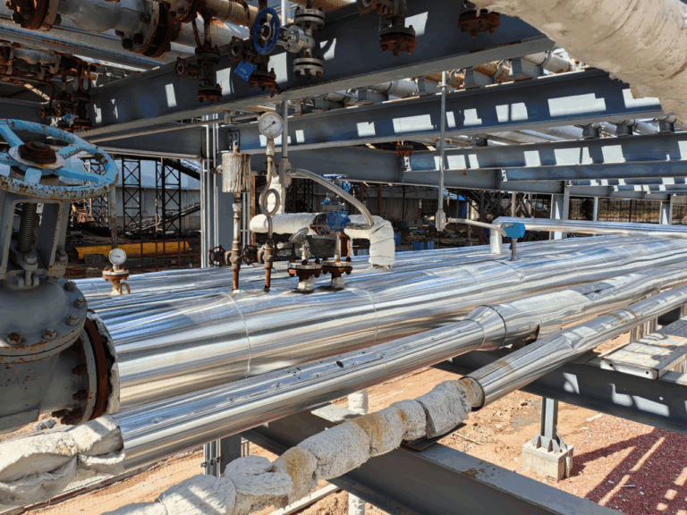
The first vortex flowmeter had been operating normally.
After the failure occurred, the field team first checked the power supply and found no obvious problem.
They then used a handheld communication tool to perform an analog output test.
The commanded output value was changed, but the loop current did not respond as expected.
After checking the wiring, load, terminals, and receiving side, the troubleshooting scope was gradually narrowed down to the converter electronics.
This is where one important distinction must be made.
An analog output test does not automatically prove that the electronics are defective.
Its purpose is to temporarily bypass the actual vortex measurement signal and determine whether the converter and output loop can respond correctly to a commanded output.
In simplified terms:
If forced output works correctly:
The problem is more likely to be associated with:
- Process conditions
- Vortex detection
- Sensor signal
- Meter configuration
- Measurement parameters
If forced output does not work correctly:
Continue checking:
- Power supply
- Wiring polarity
- Terminal connections
- Loop resistance/load
- Output configuration
- Receiving channel
- Converter electronics
In the original case, the investigation eventually pointed to the electronic unit.
A Note About Manufacturer-Specific Test Functions
The test tools and menu names used in this case belong to specific products.
For example, some Yokogawa vortex flowmeters provide analog output loop-testing functions, and current VY-series documentation includes a function identified as J10 Test analog output.
However, test procedures, menu names, test points, allowable loads, and acceptance criteria vary between manufacturers and product series.
Therefore:
Do not assume that a diagnostic procedure for one vortex flowmeter applies directly to another model.
Always follow the appropriate manufacturer documentation.
3. Replacing the Electronics Is Not the End of the Repair
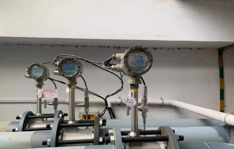
After the electronic unit was replaced, the meter output returned.
But the job was not finished.
One of the most common mistakes after replacing vortex flowmeter electronics is assuming that restoring the output means the instrument has been completely restored.
A vortex flowmeter contains much more configuration information than simply pipe size and measuring range.
Depending on the manufacturer and model, important parameters may include:
- Pipe size
- Measuring range
- Engineering units
- Sensor or instrument factor
- Fluid type
- Density settings
- Temperature and pressure compensation
- Low-flow cutoff
- Damping
- Alarm direction
- Pulse output settings
- Analog output mode
The exact parameters that must be restored depend on the specific instrument, its original datasheet, configuration backup, and manufacturer documentation.
Parameters That Deserve Special Attention
| Parameter | Why It Matters |
|---|---|
| Pipe size, range and engineering units | Incorrect values can produce an apparently valid output with the wrong flow reading |
| Sensor or meter factor | May be associated with a specific sensing assembly and should not be entered from memory |
| Low-flow cutoff | An excessively high value can make legitimate low flow appear as zero |
| Damping | Excessive damping can make the meter respond too slowly |
| Output mode | Incorrect configuration can affect DCS indication or totalization |
| Alarm direction | Can change how the control system interprets a meter fault |
After restoring the configuration, complete the manufacturer-required self-diagnostics, loop tests, and functional checks.
Whether formal recalibration or verification is required depends on the instrument’s application and the plant’s metrology or quality requirements.
Production urgency may explain why a meter is temporarily returned to service quickly. It does not justify permanently skipping verification.
4. Case 2: A Vortex Flowmeter Fails After One Month in Superheated Steam
The second case looked similar from the control room:
The flow reading went to zero.
But the failure mechanism was completely different.
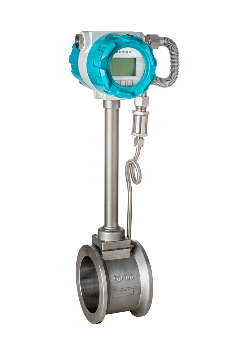
This vortex flowmeter had been installed on a superheated steam line and had only been in operation for a relatively short period.
During troubleshooting, the converter was not receiving a normal detection signal.
After the process was shut down and the required isolation, depressurization, and cooling procedures were completed, the meter was inspected.
Abnormalities were found around the insulation or sealing area of the sensing element, together with damage to the lead wires.
After comparing the actual process temperature with the instrument configuration, the maintenance team attributed the failure to a temperature-selection mismatch.
So although both meters appeared to have the same symptom—
“The vortex meter reads zero.”
—the first fault was associated with the converter/output side, while the second was associated with the sensing side and its suitability for the process temperature.
5. Never Apply a Universal Temperature Limit to All Vortex Flowmeters
A common mistake is to use rules such as:
“Standard vortex meters are suitable below 250°C, while high-temperature versions are suitable below 350°C.”
That may be true for certain products, but it is not a universal industry rule.
Temperature limits depend on factors such as:
- Manufacturer
- Product series
- Sensor construction
- Wetted materials
- Sealing materials
- Electronics arrangement
- Integral or remote configuration
Some publicly available specifications for certain Yokogawa high-temperature vortex products, for example, extend to approximately 450°C.
But that number applies only to the corresponding product configuration. It should never be copied directly to another vortex flowmeter.
The correct question is not:
“What temperature can vortex flowmeters handle?”
It is:
“What temperature can this exact vortex flowmeter configuration handle?”
6. Do Not Identify a High-Temperature Version by Appearance Alone
Experienced technicians sometimes make an initial judgment from the physical construction of a meter.
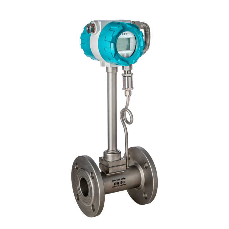
For example, they may look at the distance between the sensing body and the converter and assume that a longer extension indicates a high-temperature design.
It can be a useful visual clue.
But it is not proof.
Similar extended structures may be used for:
- High-temperature service
- Low-temperature service
- Remote electronics
- Thermal isolation
- Other manufacturer-specific designs
There is no universal dimensional rule that allows you to identify a high-temperature vortex flowmeter simply by looking at it.
For high-temperature steam service, verify at least:
1. Complete model code
Do not check only the basic series name.
2. Permitted process temperature
Compare the manufacturer’s limit with the actual operating and upset conditions.
3. Ambient temperature limit
High process temperature can also increase the temperature around the electronics.
4. Sensor and sealing materials
Different sensor and sealing constructions can have different thermal limitations.
5. Integral or remote configuration
The arrangement of the electronics can significantly affect temperature suitability.
6. Insulation boundaries
Incorrect insulation can transfer excessive heat toward components that were not designed for it.
7. Thermal isolation of the electronics
8. Manufacturer-specified mounting orientation
A meter that looks like a high-temperature version is not necessarily suitable for the actual process temperature.
If the nameplate, procurement datasheet, and manufacturer documentation do not agree, resolve the configuration before returning the instrument to service.
7. Sometimes a Zero Reading Does Not Mean the Flowmeter Has Failed
The first two cases involved component problems.
But there is another very common situation:
The vortex flowmeter is working, but the process is outside its effective measuring range.
A vortex flowmeter determines flow from the frequency of vortices generated downstream of the bluff body.
Within the usable measuring range, vortex shedding frequency is related to average flow velocity.
But when the actual velocity becomes too low, the vortex signal may become too weak or unstable for reliable measurement.
The displayed flow may then become very small—or simply drop to zero.
A similar symptom can occur when the configured low-flow cutoff is too high.
Do Not Immediately Lower the Low-Flow Cutoff
Lowering the cutoff value is not always the correct solution.
First investigate whether the actual operating conditions are appropriate for the meter.
Possible causes include:
- Oversized flowmeter
- Reduced plant load
- Insufficient flow velocity
- Partially filled liquid pipe
- Gas-liquid two-phase flow
- Incorrect flow direction
- Changes in density or viscosity
- Strong mechanical vibration
- Operation close to the meter’s lower measuring limit
If the flowmeter continuously operates near the bottom of its measuring range, the better solution may be to reconsider the meter sizing and actual process load rather than simply forcing the instrument to display every weak signal.
8. Trace the Signal Chain Before Replacing Parts
The two cases do not provide two universal fault answers.
They provide a troubleshooting method.
When somebody reports that a vortex flowmeter “shows zero,” first determine where the zero appears.
Then trace the measurement chain until you find the point where the expected signal disappears.
Practical Troubleshooting Logic
| What You See | Check First | Investigate Next |
|---|---|---|
| Local display is blank and loop current is absent | Power, polarity, terminals and load | Wiring and electronics |
| Local display is normal but DCS reads zero | Compare local output, analog signal and pulse signal | Isolator, I/O channel, scaling and configuration |
| Output test works but actual flow remains zero | Diagnostics and process conditions | Low-flow limit, parameters and sensing element |
| Meter fails shortly after installation in high-temperature service | Actual process temperature and complete model code | Materials, seals, remote configuration and insulation |
This layered approach prevents one of the most expensive troubleshooting habits in instrumentation:
Replacing parts before identifying the failed layer.
9. Avoid “Touch Tests” on the Sensor Leads
Another field practice deserves special attention.
Do not touch sensing-element leads with your fingers in an attempt to generate a so-called “induced signal.”
This method is not repeatable and can easily lead to a false diagnosis.
It may also introduce electrostatic damage and is inappropriate in hazardous, high-temperature, or energized environments.
Reading the instrument’s diagnostic information and performing manufacturer-approved simulation or loop tests is generally a much more reliable approach.
10. A Practical Vortex Flowmeter Troubleshooting Sequence
When a vortex flowmeter suddenly shows zero or loses its indication, a practical troubleshooting sequence is:
Step 1 — Define the symptom precisely
Determine whether the problem is:
- Blank local display
- Zero local flow indication
- Missing 4–20 mA signal
- Missing pulse output
- Zero indication only in the DCS
Step 2 — Check power and the output loop
Verify:
- Supply voltage
- Polarity
- Wiring
- Terminals
- Loop load
- Receiving channel
Step 3 — Perform manufacturer-approved diagnostic or output tests
Determine whether the converter and output loop can respond independently of the actual vortex signal.
Step 4 — Check process conditions and configuration
Review:
- Actual flow rate
- Flow velocity
- Meter sizing
- Low-flow cutoff
- Fluid properties
- Temperature
- Pressure
- Relevant configuration parameters
Step 5 — Inspect the sensing side only when justified
If the previous checks point toward the sensor, inspect the sensing element according to the manufacturer’s maintenance procedures and plant safety requirements.
The purpose of this sequence is simple:
Find the signal breakpoint before deciding what to repair.
Final Takeaway
Two vortex flowmeters can show exactly the same symptom:
Zero flow.
Yet one may have a problem in the converter electronics, another may have a damaged sensing element caused by unsuitable temperature selection, and a third may have no instrument failure at all—the actual process flow may simply be below the effective measuring range.
That is why good vortex flowmeter troubleshooting should never begin with:
“Which part should we replace?”
It should begin with:
“Where did the signal disappear?”
Put the local display, analog output, pulse output, DCS indication, actual valve position, process flow, temperature, and pressure on the same timeline.
Once you do that, the location of the fault often becomes much clearer.
Safety Note: For high-temperature, pressurized, hazardous-fluid, or explosion-protected applications, follow the site’s permit, isolation, depressurization, cooling, and hazardous-area requirements before opening the enclosure, disconnecting wiring, or removing the flowmeter.