Overview
When wiring in non-explosion-proof zones, it’s crucial to prevent intersections with other areas such as explosion-proof zones, high-voltage zones, low-voltage signal zones, and water/gas pipeline areas. The primary goal is to avoid interference, mitigate safety risks like leakage or short circuits, and ensure system stability. This can be achieved through systematic design focused on physical isolation, path planning, and wiring standards. Below are the key approaches.
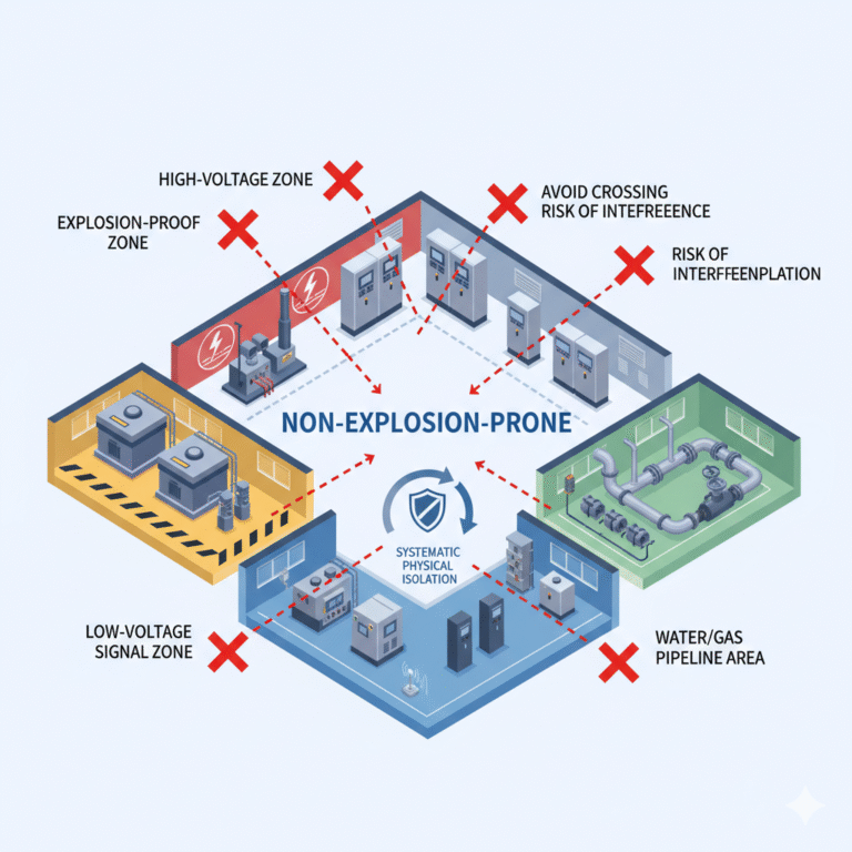
1. Identifying Key Areas to Avoid Crossings
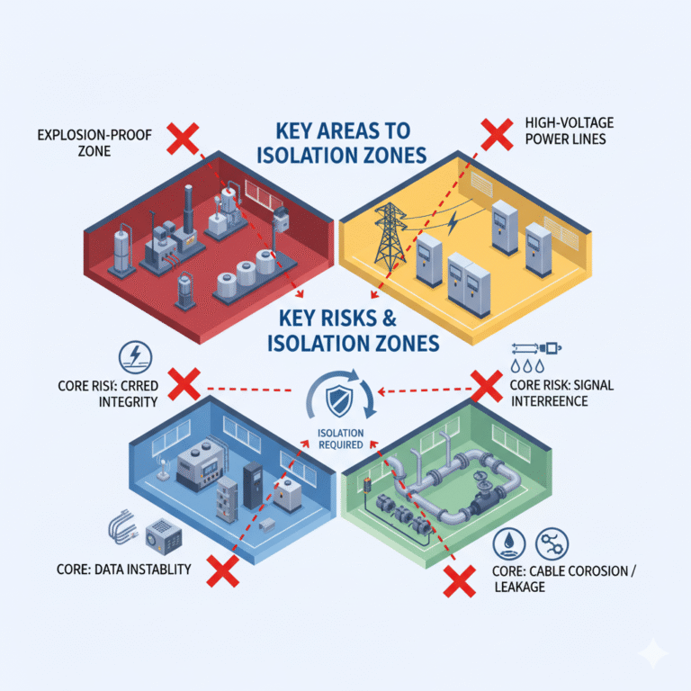
The first step is to define the critical areas where wiring should be kept separate, followed by tailored isolation strategies. Common areas that require isolation and their associated risks are as follows:
| Area Type | Core Risks |
|---|---|
| Explosion-Proof Zones | Although there is no risk of explosion in non-explosion-proof zones, interference from non-explosion-proof wiring may compromise the explosion-proof integrity of these lines. |
| High-Voltage Power Lines | High-voltage power lines generate strong electromagnetic fields, which can cause signal interference when crossing low-voltage lines (such as PLC signals or sensor cables). |
| Low-Voltage Signal Lines | Interference from power lines can disrupt communication and cause data instability in instrumentation. |
| Water/Gas/Oil Pipelines | If pipelines leak, they may corrode cables; vibrations can also damage the cable insulation, leading to leakage. |
| High-Temperature/High-Humidity Zones | High temperatures can accelerate cable insulation degradation, while humidity can cause short circuits due to insulation failure. |
2. Key Measures: Physical Isolation to Prevent Crossing
Physical isolation is the most direct method to avoid wire crossings. This can be achieved through spatial layering, protective structures, and path separation.
2.1 Spatial Layering: Separate Wiring by Voltage and Cable Type
Wires should be separated vertically or horizontally to ensure no direct crossing:
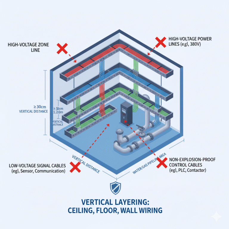
Vertical Layering (Ceiling, Floor, Wall Wiring):
High-voltage power lines (e.g., 380V motor lines, distribution cabinet main lines) should be routed along the bottom layer of cable trenches or top layer of wall-mounted trays (height ≥2.5m).
Non-explosion-proof control cables (e.g., PLC power lines, contactor control lines) should go in the middle layer (height 1.5–2.0m).
Low-voltage signal cables (e.g., sensor lines, communication lines) should be placed in the uppermost layer (height ≤1.2m), with at least a 30cm vertical distance from power cables.
Water/gas pipelines should be routed separately, with a minimum vertical distance of 50cm from cables.
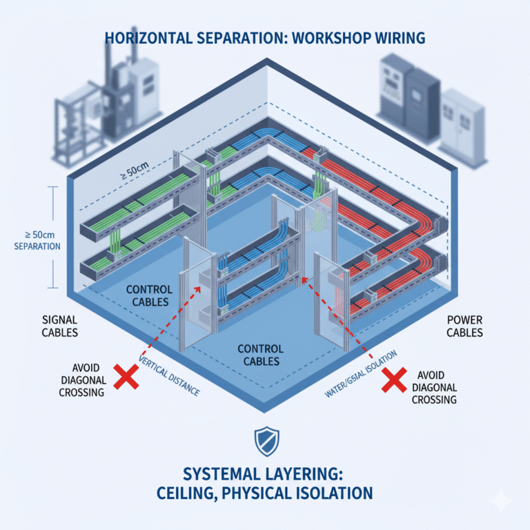
Horizontal Separation (Workshops or Control Rooms):
Use metal barriers or insulated partitions to create independent wiring channels for power, control, and signal lines. These channels should be spaced ≥50cm apart. For example, place power cables on one side of the workshop (east side), control cables in the middle, and signal cables on the opposite side (west).
2.2 Structural Isolation: Using Dedicated Wiring Supports
To achieve “physical separation,” different types of wiring supports (e.g., cable trays, conduits, cable ducts) should be used to prevent direct contact between non-explosion-proof wiring and other zones:
Cable Trays:
Non-explosion-proof power lines and signal cables should be isolated using metal cable trays with internal partitions. These trays should have at least two chambers: one for high-voltage lines and the other for low-voltage signal cables, ensuring no direct contact.Conduits:
When wiring passes through walls or floors, it should be enclosed in galvanized steel or PVC fire-resistant conduits. The conduit should contain only the same type of cable (e.g., control cables, not a mix of power and signal cables). If different zones must share the same wall penetration, use fire-resistant sealants or insulating partitions to prevent contact between conduits.Cable Ducts:
Signal lines should be routed through sealed metal ducts to prevent electromagnetic interference. These ducts must be at least 30cm horizontally and 15cm vertically away from high-voltage cable trays.
3. Auxiliary Measures: Optimizing Path Planning and Wiring Details
In situations where it’s impossible to completely avoid nearby wiring, such as parallel runs (but not crossing), optimization of the path and design details can help reduce interference risks.
3.1 Path Planning: Avoiding Diagonal or Vertical Crossings
Avoid Diagonal Crossings:
Cables should always be routed parallel to each other, and crossings at angles should be avoided, as they create points where electromagnetic coupling can occur, increasing interference.Distance: When parallel wiring is necessary, low-voltage signal cables should be placed no more than 10 meters parallel to high-voltage cables, maintaining a distance of at least 30cm. If the distance exceeds 10 meters, a metal shielding plate should be placed between them to block electromagnetic radiation.
Avoid Hazardous Areas:
Non-explosion-proof cables should avoid high-risk areas such as pipeline joints, high-temperature equipment (e.g., ovens or heaters), and vibrating machinery (e.g., pumps or fans), to prevent damage caused by leaks, heat degradation, or vibration-induced wear.
3.2 Wiring Details: Correct Cable Selection and Connections
Cable Selection:
Low-voltage signal cables should preferably be shielded twisted pair cables, with double shielding (internal mesh and external foil). The shielding should be grounded at one end to reduce interference from adjacent power lines.Avoid using uninsulated or low-quality cables, as insulation breakdown can lead to short circuits when crossing with other lines.
Connection Standards:
Cable joints should be made inside dedicated junction boxes or terminal boxes, ensuring they are sealed to prevent dust or moisture ingress. Junction boxes should also be kept at least 50cm away from those used in other zones. Cable installation should allow enough slack to prevent stretching but avoid creating tangles or knots inside trays or ducts.
3.3 Clear Marking: Preventing Misconnections and Crossings
Marking:
All wiring trays, conduits, and ducts should be clearly marked, such as “Non-Explosion-Proof – Control Cable” or “Non-Explosion-Proof – Signal Cable,” with labels placed every 10 meters and at every bend.For crossings at boundaries between different zones (e.g., non-explosion-proof and explosion-proof areas), use warning signs like yellow and black caution tape or “No Crossing” labels to clearly demarcate wiring zones and avoid mix-ups during maintenance.
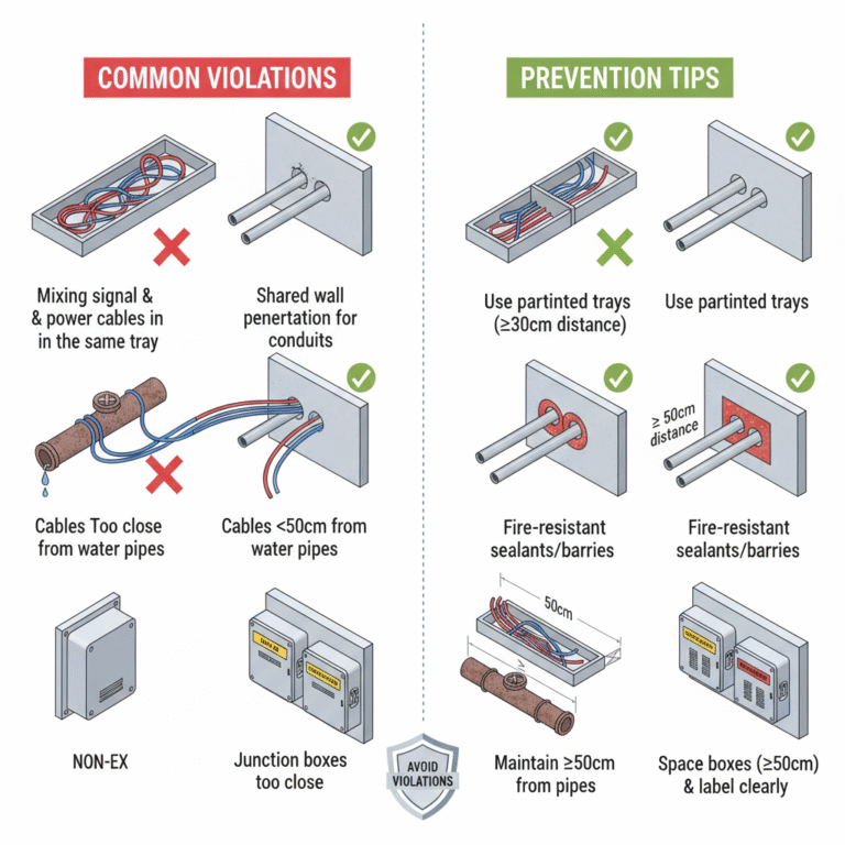
4. Common Violations and How to Avoid Them
| Common Violations | Core Risks | Prevention Tips |
|---|---|---|
| Mixing non-explosion-proof signal and power cables in the same tray | Interference leading to communication failure or false instrument readings | Use partitioned trays or separate trays, with at least 30cm distance. |
| Shared wall penetrations for non-explosion-proof and explosion-proof conduits | Risk of compromising explosion-proof integrity or water/dust ingress | Use fire-resistant sealants or insulation barriers to separate conduits. |
| Parallel routing of non-explosion-proof cables and water pipes with less than 30cm spacing | Leaks from water pipes can cause short circuits or cable corrosion | Ensure cables are at least 50cm away from water pipes or run cables underneath. |
| Non-explosion-proof and explosion-proof junction boxes placed too close together | Interference between zones or incorrect connections | Maintain at least 50cm distance and ensure clear labeling for all junction boxes. |
Conclusion
To avoid crossings between non-explosion-proof wiring and other zones, the core principle is physical separation first (using layered structures or dedicated wiring supports), followed by path optimization (parallel wiring with shielding) and detail-oriented protection (cable selection and clear marking). These strategies ensure safety by preventing leakage, short circuits, and system interference, ultimately maintaining system stability.