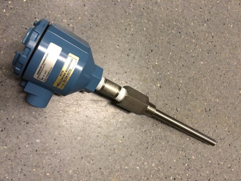
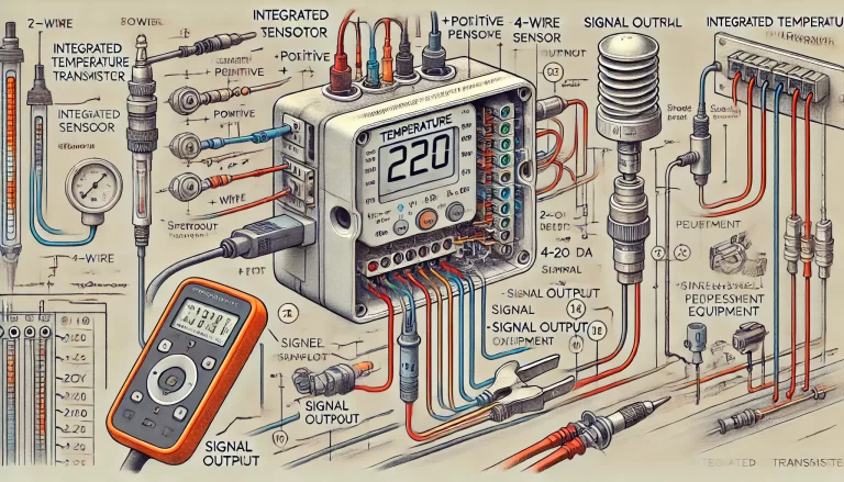
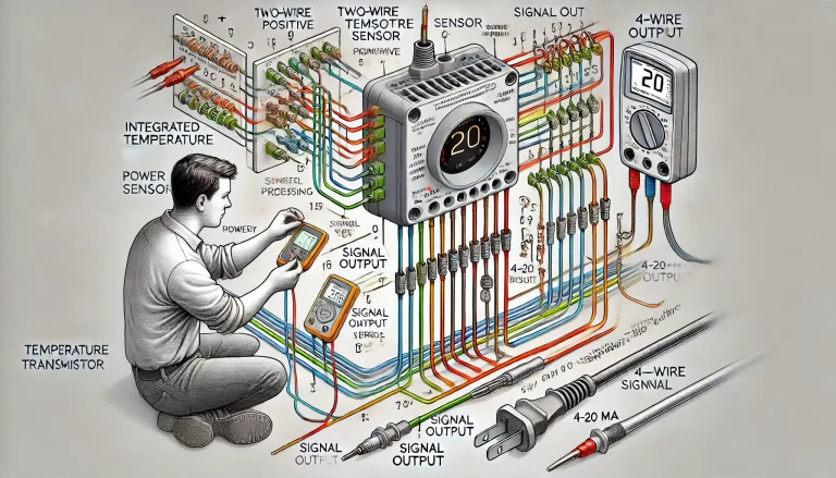
An integrated temperature transmitter plays a critical role in converting temperature signals from sensors (like thermocouples or RTDs) into standardized electrical signals (commonly 4-20 mA). Proper wiring is essential to ensure accurate data transmission and long-term reliability. Below is a detailed guide on wiring an integrated temperature transmitter.
1. Preparation Before Wiring
Before starting the wiring process, ensure the following:
- Voltage Compatibility: Check the transmitter’s input voltage specifications, usually 24V DC. Ensure your power source matches these requirements.
- Sensor Type Compatibility: Confirm that the transmitter matches the type of temperature sensor being used (e.g., RTD, thermocouple) and that the signal configuration (2-wire, 3-wire, or 4-wire) is properly identified.
- Correct Tools: Have appropriate tools, including screwdrivers, wire strippers, multimeters, and process calibrators, on hand to assist with testing and troubleshooting.

2. Wiring Configurations
The wiring method depends on the transmitter’s design. Below are two common configurations:
Two-wire Configuration:
- The power supply and signal output share the same two wires.
- Often used for 4-20 mA loop-powered transmitters.
Three-wire Configuration:
- Common with RTD sensors for more accurate readings.
- The third wire is used to compensate for wire resistance, which improves accuracy over longer distances.
3. Wiring Procedure and Best Practices
- Identify Terminals: Check the transmitter’s manual for labeled terminals. Typical terminals include:
- + (Positive): For the power supply.
- – (Negative): For the return/ground.
- Signal output terminals: (if separated from the power supply).
- Ensure Correct Polarity:
- Properly connect the positive (+) and negative (–) terminals.
- Reversed polarity may cause malfunction or permanent damage to the transmitter.

4. Shielding and Grounding Considerations
- Use Shielded Cables: To reduce electrical noise and interference, shielded cables are recommended, especially in noisy environments.
- Grounding:
- Connect the shield only at one end, typically at the signal processing equipment end. This prevents ground loops, which could introduce interference.
- Make sure the transmitter and sensor body are adequately grounded for safety and noise reduction.
5. Routing the Signal and Power Wires
Separate Signal and Power Wires:
- Avoid running the signal cables parallel to power cables to prevent electromagnetic interference (EMI).
- If signal and power lines must cross, they should do so at right angles to minimize interference.
Use Cable Ties: Secure all cables and ensure that no wires are loose or exposed. This prevents accidental disconnection or damage to the wiring.
6. Installation Location and Environment
- Environmental Protection: Install the transmitter in a well-ventilated, dry location, away from heat, humidity, and corrosive gases that could affect performance.
- Mounting: Make sure the transmitter is properly mounted to minimize mechanical stress on the wires and connectors.
7. Testing and Commissioning
- Check Connections: After wiring, visually inspect all terminals to ensure no loose or improperly connected wires.
- Power On: Apply power to the transmitter and observe for any signs of malfunction (e.g., incorrect readings, no output signal).
- Output Verification: Use a multimeter or process calibrator to measure the output signal (4-20 mA). Verify the transmitter is sending the correct output corresponding to the measured temperature.

8. Maintenance and Troubleshooting
Regular Inspections: Periodically check all connections for corrosion, wear, or loose terminals.
Signal Issues:
- If the transmitter output is incorrect, check the power supply voltage and sensor connections.
- Use a multimeter to measure the loop current (4-20 mA) and confirm it matches the expected value.
Electrical Noise Issues: If readings are fluctuating, review the cable shielding and grounding, ensuring there are no ground loops or EMI issues.

Conclusion
Following these wiring practices ensures reliable performance from your integrated temperature transmitter. Proper preparation, correct terminal connections, shielding, and grounding are essential to avoid common issues like electrical noise and measurement errors. Additionally, regular maintenance helps prolong the transmitter’s life and ensures accurate readings throughout its operation.
By adhering to these detailed guidelines, you can ensure a smooth and efficient installation process, reducing downtime and preventing costly troubleshooting in the future.
