Abstract
Averaging Pitot tube flowmeters are often applied in steam measurement due to their simple structure and low pressure loss. However, when used for wet steam, they frequently produce significant measurement errors. This paper analyzes the mechanism of error generation, highlights the impact of incorrect installation, and provides practical recommendations for improving accuracy. It also compares the suitability of averaging Pitot tubes with alternative flowmeter types.
1. Introduction
Steam is widely used in industrial heating, power generation, and chemical processes. Accurate steam flow measurement is essential for energy cost accounting, process control, and equipment efficiency evaluation.
Despite their popularity, averaging Pitot tube flowmeters often exhibit errors greater than ±5% when measuring steam. The main reasons include:
Wet steam properties (two-phase flow).
Incorrect probe installation.
Sensitivity to operating conditions (pressure/temperature fluctuations).
Structural limitations of single-point or limited multi-point pressure sampling.
2. Characteristics of Wet Steam
2.1 Definition
Wet steam: Mixture of saturated vapor and entrained liquid droplets/films.
Dryness fraction (x): Ratio of vapor mass to total mass (0 ≤ x ≤ 1).
Dry steam: No liquid phase present (x=1).
Superheated steam: Dry steam further heated above saturation temperature.
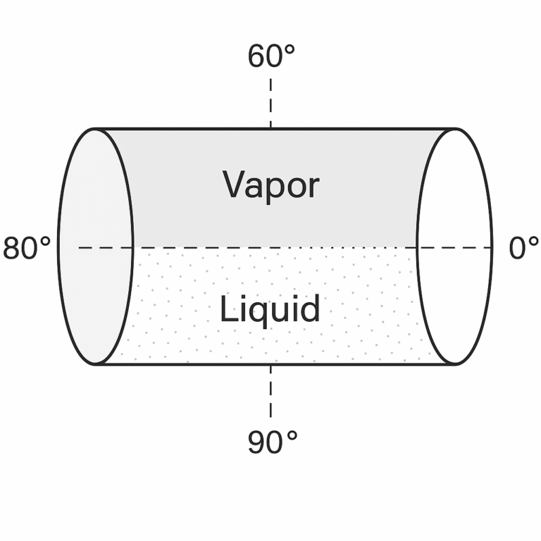
2.2 Phase Distribution in Horizontal Pipelines
Upper half (0°–90° and 270°–360°): Vapor-dominant, suitable for sampling.
Lower half (90°–270°): Liquid accumulation (droplets, liquid film, pooling).
3. Error Mechanisms of Incorrect Installation
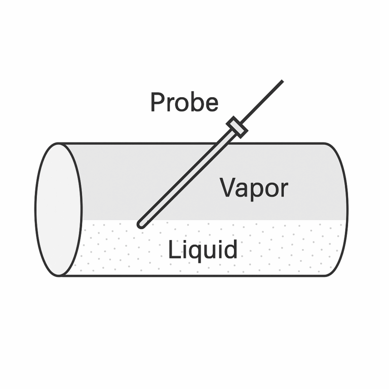
When the averaging Pitot tube is inserted at 45° upward from the bottom half, the probe falls directly into the liquid-rich zone, causing multiple types of errors.
3.1 Pressure Sampling Distortion
Total pressure error: Impact of high-density liquid on the pressure port leads to artificially high readings and fluctuations.
Static pressure error: Ports blocked or covered by liquid film, producing lower or unstable values.
3.2 Flow Velocity Miscalculation
Based on Bernoulli’s equation (single-phase assumption).
Low dryness (x < 0.9): Severe overestimation (up to +50%).
High dryness (x ≈ 0.95–0.99): Smaller but still positive deviation (+10% to +30%).
Results do not represent actual average vapor velocity.
3.3 Long-Term Instability
Blockage of ports by rust/scale carried by condensate.
Erosion from liquid droplets, leading to deformation and further measurement drift.
3.4 Mass Flow Calculation Error
Since mass flow is calculated as:
Q=v×A×ρ
(where v = velocity, A = pipe cross-sectional area, ρ = density),
errors in v directly lead to over- or under-reporting of steam consumption, distorting cost accounting and process control.
4. Quantitative Error References
Industrial data shows that installing the probe in the lower half (45° upward) produces the following deviations compared with correct installation (upper half, 45°–135°):
Table 1 — Typical Measurement Error vs. Steam Dryness Fraction
| Dryness Fraction (x) | Typical Error Range (Incorrect Installation) |
|---|---|
| 0.80 – 0.90 | +30% to +80% |
| 0.90 – 0.95 | +25% to +75% |
| 0.95 – 0.98 | +10% to +30% |
| 0.98 – 0.995 | +5% to +15% |
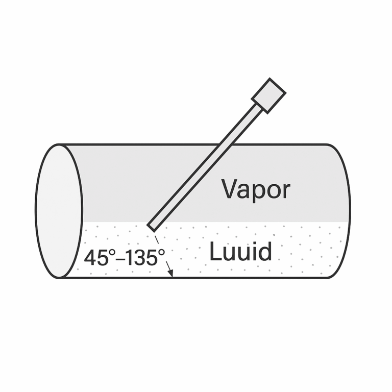
5. Correct Installation and Design Recommendations
5.1 Installation Orientation
Probe should be inserted in the upper half (45°–135° from horizontal).
Total pressure port must face flow direction to capture vapor-dominant region.
5.2 Supporting Design Improvements
Avoid U-tube/cold condensate chambers; use high-temperature silicone oil filled DP transmitters.
Apply CFD (Computational Fluid Dynamics) simulation for optimal placement in critical applications.
Maintain straight pipe lengths: 10D–40D upstream, 5D downstream.
6. Limitations of Averaging Pitot Tubes for Steam
Accuracy grade: 1.5–2.5 (typically).
Error amplification: At low velocity (<20% of design), error exceeds ±5%.
Pipe size sensitivity: Suitable only for DN300+; poor performance in small pipes.
Not recommended for trade settlement due to insufficient accuracy.
Table 2 — Comparison of Flowmeter Types for Steam Applications
| Flowmeter Type | Typical Accuracy | Suitable Applications | Limitations |
|---|---|---|---|
| Averaging Pitot | ±2.5%–5% | DN300+ main steam pipelines, energy statistics | Not for trade settlement, unstable at low velocity |
| V-Cone | ±0.5%–1.0% | Trade settlement, stable under wet steam | Higher cost |
| Vortex | ±1.0%–1.5% | Medium-size pipelines, broad adoption | Sensitive to vibration |
| Orifice Plate | ±1.0%–2.0% | Wide use, standard method | High pressure loss |
| Swirl/Vortex Precession | ±0.5%–1.0% | Trade and precise control | Higher installation cost |
7. Conclusion
Measurement errors in steam flow using averaging Pitot tubes largely stem from incorrect installation in liquid-rich zones.
Proper orientation (upper half, 45°–135°) and optimized design can limit errors to within ±2.5%, but structural limitations remain.
Averaging Pitot tubes are best reserved for coarse energy monitoring in large pipelines.
For trade settlement or high-accuracy applications, V-Cone, vortex, or orifice plate flowmeters are recommended.