1. What Is Grounding Resistance?
Grounding resistance refers to the resistance encountered by electrical current as it flows from a grounding device into the earth and disperses either toward another grounding electrode or into distant ground. It includes:
The resistance of the grounding conductor and electrode,
The contact resistance between the grounding electrode and soil,
The resistance of the earth itself between two grounding points or toward an infinitely remote point.
Grounding resistance is a key indicator of how well electrical equipment is connected to the earth, ensuring both electrical safety and system reliability.
2. Types of Grounding
Grounding can be categorized into four main types:
Protective Grounding
For metal enclosures of electrical devices or structures (e.g., poles, supports) that might become live due to insulation failure, to prevent electric shock.Anti-static Grounding
Used to safely dissipate static electricity from flammable storage tanks, pipelines, or electronic devices.Lightning Protection Grounding
Connects devices like lightning rods to the earth, directing high-voltage lightning discharges safely into the ground.Functional (Working) Grounding
Connects specific parts of a power system (e.g., transformer neutral points) to the ground, either directly or through devices like arc-suppression coils or resistors.
3. Standard Requirements for Grounding Resistance
According to national and industry standards:
| Type of Grounding | Maximum Allowed Resistance |
|---|---|
| Independent lightning protection | ≤ 10 Ω |
| Independent safety/protective grounding | ≤ 4 Ω |
| Independent AC working grounding | ≤ 4 Ω |
| Independent DC working grounding | ≤ 4 Ω |
| Anti-static grounding | ≤ 100 Ω |
| Shared/Combined grounding system | ≤ 1 Ω |
⚠️ Note: Ground wires for lightning rods are usually allowed to be shared with anti-static systems if their resistance is low enough, since the lightning path will dominate the discharge.
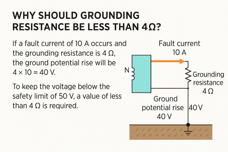
4. Why Is 4Ω the Critical Threshold?
(1) Safety Voltage Considerations
According to Ohm’s Law:
V=I×R
If a fault current of 10A occurs and the grounding resistance is 4Ω, the potential rise at the ground point will be:
V=10×4=40V
Standards typically stipulate that the voltage between any two conductors or between a conductor and earth must not exceed 50V AC (50–500Hz) under fault conditions. Thus, 4Ω is a safe upper limit to prevent electric shock.
(2) Compliance with Laws and Industry Standards
Electrical installations must follow strict safety codes, such as:
GB/T 50065: Code for Grounding Installation
GB 50057: Code for Lightning Protection Design
These values are based on long-term operational data and real-world accident analysis. Violations may cause legal risks and severe safety hazards.
5. Factors That Affect Grounding Resistance
Soil Resistivity: High in dry, sandy, or rocky areas; low in moist, clay-rich soils.
Soil Moisture and Temperature: Moist and warm soils conduct better.
Depth and Size of Grounding Electrodes: Longer, deeper rods lower resistance.
Number and Shape of Grounding Electrodes: Multiple vertical rods or a horizontal grid improve contact area and reduce resistance.
Materials Used: Copper-bonded steel, galvanized steel, or special compounds can enhance conductivity.
6. How to Measure Grounding Resistance
The most common measurement method is the Three-Point Fall-of-Potential Method, involving:
E (Earth electrode): The grounding electrode under test.
P (Potential electrode): Placed 5–10 meters away.
C (Current electrode): Placed 30–50 meters away from the E electrode.
Step-by-Step:
Disconnect the grounding electrode from the system.
Drive two auxiliary probes (P and C) into the ground in a straight line.
Connect all terminals to a ground resistance tester (e.g., Fluke 1625).
Take multiple readings by moving the potential probe (P) and verify stability.
Use the average of stable values as your measured resistance.
7. Typical Application Scenarios
Lightning Protection: Minimizes the voltage rise during a lightning strike to safely divert energy to ground.
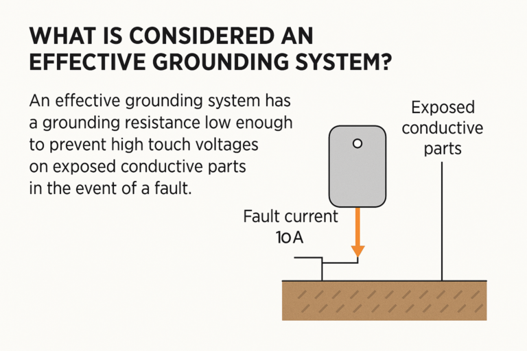
Appliance Safety Grounding: In appliances like refrigerators and washing machines, the metal shell must be grounded. A low grounding resistance ensures any leakage current flows safely to ground instead of through a person.
Static Dissipation: Prevents electrostatic discharge that could damage sensitive electronic equipment or ignite flammable gases.
8. Conclusion
Maintaining a grounding resistance below 4Ω is not arbitrary—it’s a scientifically backed safety threshold that protects equipment and lives. Understanding grounding principles, applying correct installation methods, and performing regular measurements are essential for any facility where electrical safety matters.