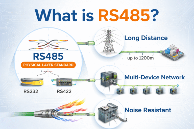
Why RS485 Communication Fails Without 120Ω Termination (And How to Fix It) / Instrumentation Introduction: When RS485 “Works” — Until It Suddenly Doesn’tIn many industrial projects, RS485 communication seems to work fine at the beginning.But after some time, problems start appearing:Random data errorsIntermittent disconnectionsUnstable Modbus communicationDevices going offline without clear reasonIn most cases, the root cause is surprisingly simple:👉 Missing or incorrect 120Ω termination resistor What Does the 120Ω Resistor Actually Do?RS485 is a high-speed differential communication system.The signal travels along twisted-pair cables at very high speed.When the signal reaches the end of the cable and no termination resistor is present, it reflects back — similar to an echo.This creates:Signal distortionOverlapping waveformsData misinterpretation (0 becomes 1, or vice versa)✔ Solution: Impedance MatchingA 120Ω resistor is added at both ends of the RS485 bus to match the cable impedance.👉 This ensures:No signal reflectionClean waveformStable communication “It Works Without It” — But That’s RiskyMany engineers say:“My RS485 works fine without termination.”Yes — but only under certain conditions:Very short cable (e.g., 2–5 meters)Low baud rate (e.g., 9600)Minimal electrical interference⚠️ The Problem in Real Industrial EnvironmentsIn actual projects:Cable length increases (5m → 50m or more)Baud rate increases (9600 → 115200)Electrical noise from VFDs, motors, and pumpsMore devices added to the bus👉 Without termination:Error rate increases dramaticallyCommunication becomes unreliableTroubleshooting becomes difficult How to Properly Install the 120Ω Termination Resistor1️⃣ Install Only at Both Physical EndsFor a standard RS485 daisy-chain topology: Device A —— Device B —— Device C —— Device D↑ ↑120Ω 120Ω ✔ Only the first and last device should have termination resistors❌ Do NOT add resistors at every device 2️⃣ Check Built-in TerminationMany industrial devices (flowmeters, PLCs, transmitters) already include internal termination resistors.Often controlled by DIP switch or jumperEnable ONLY at the two ends 3️⃣ Use Proper Power RatingUse at least:👉 120Ω / 0.25W resistorFor long-distance or high-load systems, consider higher rating. Common Mistakes That Cause RS485 Failure❌ No termination resistor❌ Too many termination resistors❌ Star topology instead of daisy chain❌ Poor grounding or shielding❌ Long stub lines👉 These issues often appear as “mysterious communication problems” Practical Tip from Field ExperienceIn many real projects we’ve supported:👉 More than 60% of RS485 communication issues are related to wiring and termination — not the device itself.Before replacing equipment, always check:✔ Termination✔ Wiring structure✔ Grounding Need Help With RS485 or Modbus Communication?If you are facing:Unstable RS485 communicationModbus data errorsFlowmeter / transmitter not respondingDifficult field troubleshooting👉 We can support you with:✔ RS485 wiring design✔ Communication troubleshooting✔ Compatible industrial instruments (flowmeters, transmitters with RS485 / Modbus)✔ Pre-configured solutions for stable communication Share This Story, Choose Your Platform! Contact Us Please prove you are human by selecting the truck. Request a Quote