Abstract
Radar level transmitters are widely used in chemical storage tanks, wastewater basins, and bulk solids silos. However, many engineers complain about unstable readings, false alarms, or persistent measurement errors. This article explains the underlying principles, highlights common mistakes, and provides practical guidelines to ensure accurate radar level measurement in real-world applications.
1. Working Principle of Radar Level Measurement
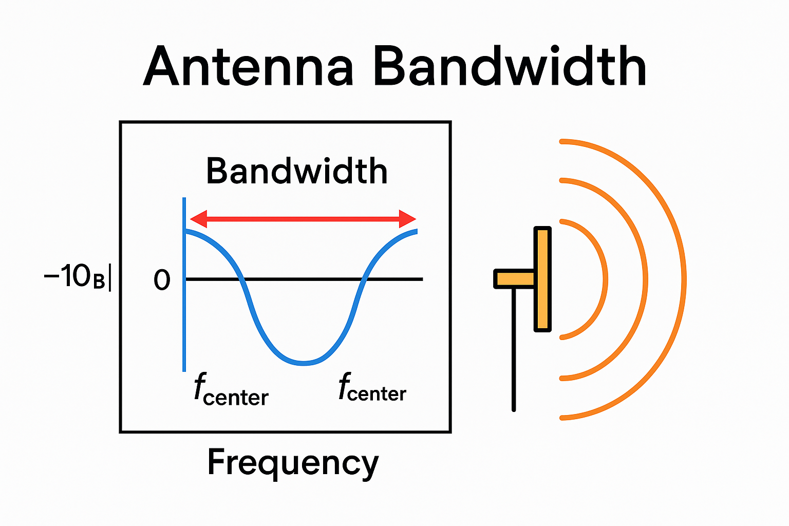
Radar transmitters emit microwave signals (commonly 6 GHz, 26 GHz, or 80 GHz). The reflected echo from the medium surface is analyzed to calculate the level.
Key influencing factors include:
Frequency: Higher frequency → narrower beam angle, higher resolution, but weaker penetration.
Dielectric constant: Higher dielectric constant → stronger reflection; low dielectric constant liquids may generate very weak signals.
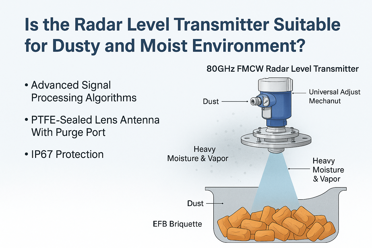
Process conditions: Foam, steam, dust, and crystallization can distort or attenuate echoes.
2. Common Misconceptions and Installation Errors
2.1 Installation Issues
Mounted too close to the tank wall → strong false echoes
Directly facing inlet → splashing and turbulence interference
Above agitators → multiple echoes
✅ Recommendation: Follow the 1/6 tank diameter rule, avoid inlets and mixers.
2.2 Medium Characteristics
Low dielectric liquids (e.g., LPG, solvents): weak reflections.
Foam: absorbs or scatters microwaves.
Solids with steep angles: irregular echoes.
✅ Recommendation:
Use high-frequency (80 GHz) or guided-wave radar for low dielectric media.
Install stilling well or waveguide tube for foamy conditions.
For solids, use narrow-beam antennas with dust protection.
2.3 Process and Environmental Disturbances
Condensation on antenna → signal loss
Heavy dust or vapor → false level
Crystallization blocking the antenna
✅ Recommendation:
Equip purge/air-blowing or heating devices to keep antenna clean.
Use radars with purge ports in extreme dust environments.
2.4 Parameter Settings
Incorrect empty/full calibration → offset errors
“False echo suppression” not enabled → unstable signals
Excessive sensitivity → noise detection
✅ Recommendation:
Always perform empty tank calibration during commissioning.
Verify real level using the echo curve.
Manually suppress false echoes when needed.
2.5 Device Capability Limitations
Low-cost radars may fail in multiple-echo environments.
✅ Recommendation: Use high-performance radars with advanced echo-processing algorithms and vendor commissioning support.
3. Engineering Practice Checklist
Selection Phase
Liquids: 26 GHz/80 GHz, dielectric constant > 2
Solids: 80 GHz, narrow beam angle
Low dielectric liquids: guided-wave radar preferred
Installation Phase
Follow 1/6 tank diameter rule
Avoid agitators and inlets
Consider stilling well or reflector plate
Commissioning Phase
Calibrate empty/full distance
Review echo curve for false echoes
Adjust gain and suppression zones
Maintenance Phase
Regularly inspect for condensation or crystallization
Clean dust or activate purge systems
Quarterly review echo curve to check parameter drift
4. Case Study
Scenario: LPG storage tank, inaccurate and fluctuating readings.
Problem: Low dielectric constant → weak signals; probe near inlet → interference.
Solution: Replaced with guided-wave radar, adjusted installation, enabled false echo suppression.
Result: Stable readings with ±5 mm accuracy.
5. Conclusion
Inaccuracy of radar level transmitters is rarely a device problem. Instead, it is often caused by process conditions, installation, or parameter settings. An excellent engineer not only understands the theory but also knows how to identify disturbances, fine-tune parameters, and optimize solutions in the field.
Accurate measurement = Technology + Experience.