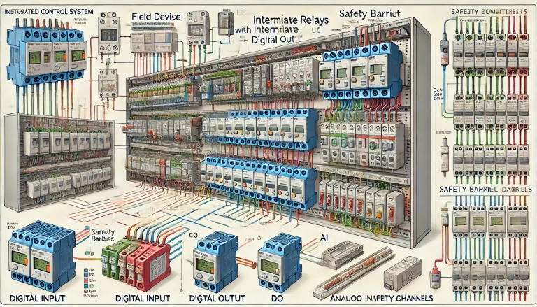
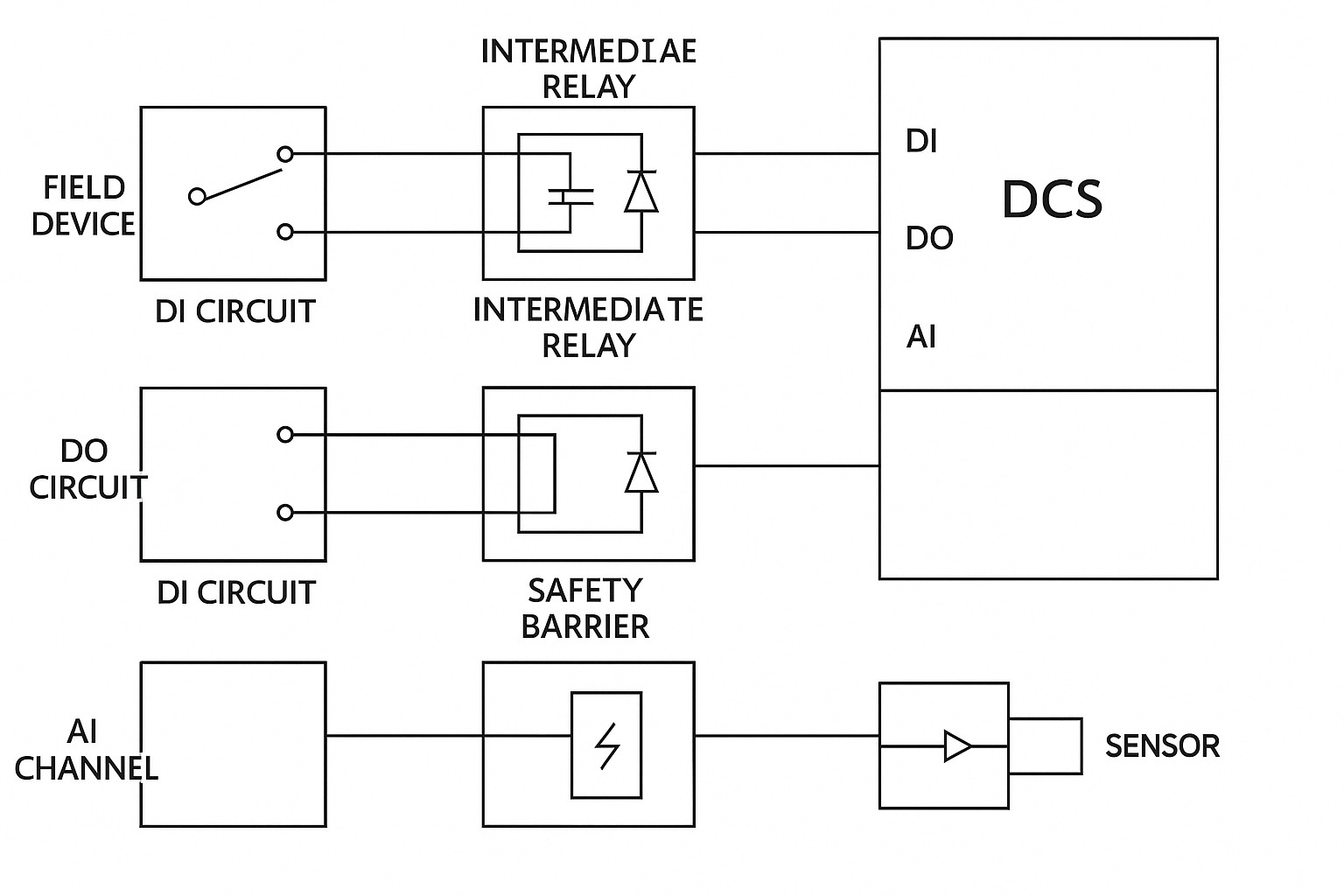
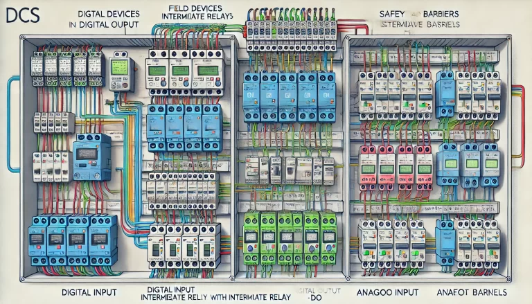
In Distributed Control Systems (DCS), the integration of intermediate relays in Digital Input (DI) and Digital Output (DO) circuits, as well as safety barriers in Analog Input (AI) channels, is a common engineering practice. These components play critical roles in enhancing system stability, safety, signal integrity, and maintainability.
This article explains the key reasons behind using these devices and how they support reliable industrial automation operations.
1. Why Are Intermediate Relays Used in DCS DI Circuits?
1.1 Electrical Isolation
Intermediate relays provide galvanic isolation between the field devices and the DCS input modules. This protects the control system from voltage surges, ground loops, or unexpected electrical faults from the field side.
1.2 Noise Immunity
In noisy industrial environments with motors, inverters, and welding equipment, relay contacts act as physical separation points that help prevent electromagnetic interference (EMI) from entering the control cabinet.
1.3 Signal Adaptation
Field devices may operate at different voltage levels (e.g., 24VDC, 48VDC, or even AC signals), while the DCS DI cards often require standardized dry contact or specific logic levels. Relays help to normalize these signals for compatibility.
1.4 Logical Interlocking
Using relays, you can create preprocessing logic such as interlocks, signal delay, or combination logic directly in the field, reducing the load on the DCS CPU and improving system safety.
1.5 Load Driving Capability
If the field signal is weak and cannot drive the DCS input reliably (e.g., due to long cable distances or high impedance), a relay can serve as a signal amplifier.
2. Why Are Intermediate Relays Used in DCS DO Circuits?
2.1 Device Protection
Field devices such as solenoid valves, contactors, and alarms may operate at different voltages or high currents that exceed the capability of the DCS DO card. Relays protect the DCS by buffering the output.
2.2 Signal Conversion
The DCS may output 24VDC logic, while the field device requires 110VAC or 220VAC. Relays allow for voltage level shifting and act as a signal converter between control logic and actual devices.
2.3 Electrical Matching
Some field equipment requires specific current loads to activate. Relays bridge the electrical characteristics between low-power control signals and high-power field loads.
2.4 Logic Implementation
Relays allow for complex logic combinations in the output circuit, enabling functions like priority control, alarm backup, or grouped activation without complex DCS programming.
2.5 Maintenance and Fault Isolation
If a DO channel fails or needs inspection, using a relay makes troubleshooting safer and easier. The relay separates field faults from the DCS and avoids damage propagation.
3. Why Do AI Channels Require Safety Barriers?
3.1 Intrinsic Safety in Hazardous Areas
When sensors are installed in explosive or flammable environments (Zone 0/1/2), intrinsically safe barriers are essential to limit the energy transferred from the safe zone to the field, preventing sparks or heat generation.
3.2 Electrical Isolation and Noise Reduction
Safety barriers provide electrical isolation between the sensor and the AI card, improving signal quality and reducing interference from surrounding equipment.
3.3 Signal Conditioning
Barriers may also include signal adaptation functions to convert sensor output to a standard range (e.g., 4–20mA), ensuring compatibility with DCS analog modules.
3.4 Equipment Protection
In case of short circuits or voltage spikes, the safety barrier acts as a first line of defense, protecting the DCS analog cards and preventing widespread equipment damage.
4. Summary Table
| Function | DI Intermediate Relay | DO Intermediate Relay | AI Safety Barrier |
|---|---|---|---|
| Electrical Isolation | ✅ | ✅ | ✅ |
| Signal Conversion/Matching | ✅ | ✅ | ✅ |
| Logic Processing | ✅ | ✅ | — |
| Load Enhancement | ✅ | ✅ | — |
| Fault Isolation | ✅ | ✅ | ✅ |
| Hazardous Area Use | — | — | ✅ |