Gas Detection Systems (GDS) are categorized as critical safety systems. Their primary functions—real-time gas concentration monitoring, alarm triggering, and emergency interlock—require extremely high reliability, fast response, and fail-safe communication.
For this reason, international and domestic standards clearly state that GDS field detectors must NOT be connected using a shared bus network, including RS-485 multi-drop wiring. A point-to-point dedicated wiring method is mandatory.
This article explains why bus communication is prohibited and what connection methods are allowed.
1. Why Bus Architecture Is Prohibited
1.1 Low communication robustness in a shared network
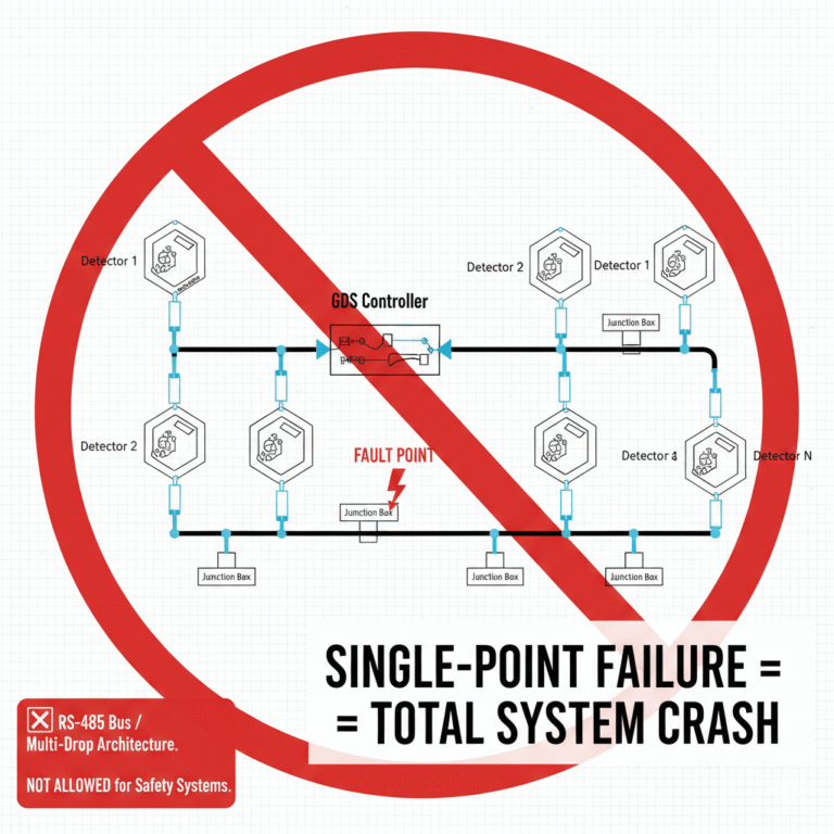
Bus systems such as RS-485 are based on a shared communication channel. All detectors communicate on the same pair of wires. If any single point—such as a connector, junction box, cable segment, or device node—fails due to:
short circuit
open circuit
poor contact
signal collision
grounding issue
the entire bus network may fail, causing all detectors to lose communication simultaneously. This is unacceptable for a safety-critical system where continuous monitoring is required.
1.2 Delayed response caused by sequential polling
A bus system must poll each detector one by one. As the number of devices increases, the communication cycle becomes longer, resulting in:
data queuing
communication latency
occasional loss of response under high load
However, a GDS must transmit alarm signals within seconds to the control room when gas concentration exceeds the limit. Bus latency may delay emergency shutdown or ventilation actions.
1.3 Not compliant with gas detection safety standards
Standards strongly discourage or directly forbid GDS bus wiring. For example:
GB/T 50493 — Design Standard for Combustible and Toxic Gas Detection Systems Requires independent signal transmission between detectors and controllers, not a multi-drop shared bus.
IEC 60079-29 series Emphasizes reliability, fault isolation, and immunity to single-point failures — which bus architecture cannot guarantee.
SIL/SIS requirements GDS is often part of a Safety Instrumented System (SIS). Bus communication cannot meet SIL verification due to the inability to isolate faults.
Therefore, using RS-485 bus architecture does not meet compliance and may be rejected during design review or site inspection.
2. Recommended Wiring Methods for GDS
2.1 Independent 4–20 mA analog signal (most widely used)
Each detector must have its own cable to transmit the 4–20 mA signal to the GDS controller or DCS/PLC. Characteristics:
Dedicated channel per detector
Fault on one line does not affect others
Fast, stable, and universally compatible
Fully compliant with safety standards
2.2 Independent relay/alarm contact output
For simple alarm-only applications, detectors may provide dry contact relay output. Still, each detector uses a separate pair of wires.
This ensures alarms remain isolated and reliable.
2.3 Point-to-point digital communication (not bus-type)
Some high-end detectors provide digital communication using RS-485 or similar, but strictly in point-to-point mode (one detector per cable).
This method is only acceptable if:
the communication link is independent
it passes required certifications
fault isolation is ensured
It is NOT the same as a multi-drop RS-485 bus.
3. Summary for End Users and EPC Customers
To ensure high reliability, fast response, and full compliance with safety standards:
❌ RS-485 bus / multi-drop architecture
Not allowed (High risk, delay, single-point failure, non-compliant)
✔ Independent point-to-point wiring
Required and compliant (4–20 mA, relay output, or point-to-point digital)
Following the correct wiring method ensures the GDS system functions safely, prevents network-wide failures, and meets regulatory requirements during engineering design, factory acceptance test (FAT), and site safety audits.