A Practical Engineering Guide with Real Case Analysis
In fluid control systems, both flow meters and control valves are widely used and often installed in series on the same pipeline. A key engineering question frequently arises during design:
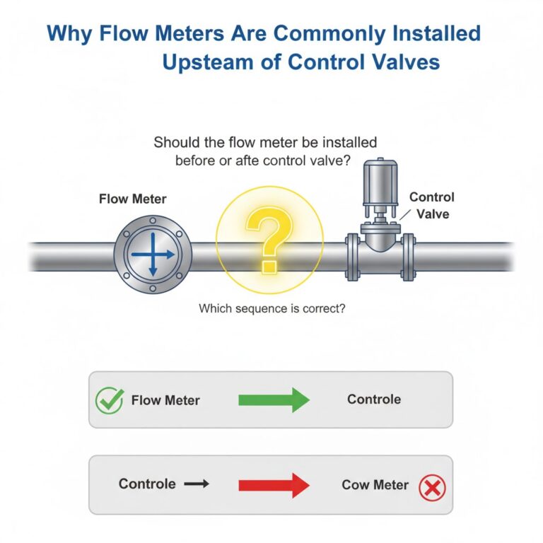
Should the flow meter be installed before or after the control valve?
Although the answer may vary depending on special conditions, in most cases—especially for electromagnetic, vortex, ultrasonic or differential-pressure flow meters—the recommended installation sequence is:
💡 Flow meter → Control valve
This article explains why, using both theoretical analysis and a real industrial case.
1. Real Case: Electromagnetic Flow Meter Installed Downstream of a Control Valve
At a fuel ethanol plant in Henan, China, fermented alcohol solution is pumped into a vacuum distillation tower. For accurate feed control, the system included:
An electromagnetic flow meter
A control valve located upstream of the meter
After some time in operation, two major problems appeared:
Flow readings were consistently higher than actual flow, with significant noise.
The liner inside the flow tube developed bubbles and partial delamination.
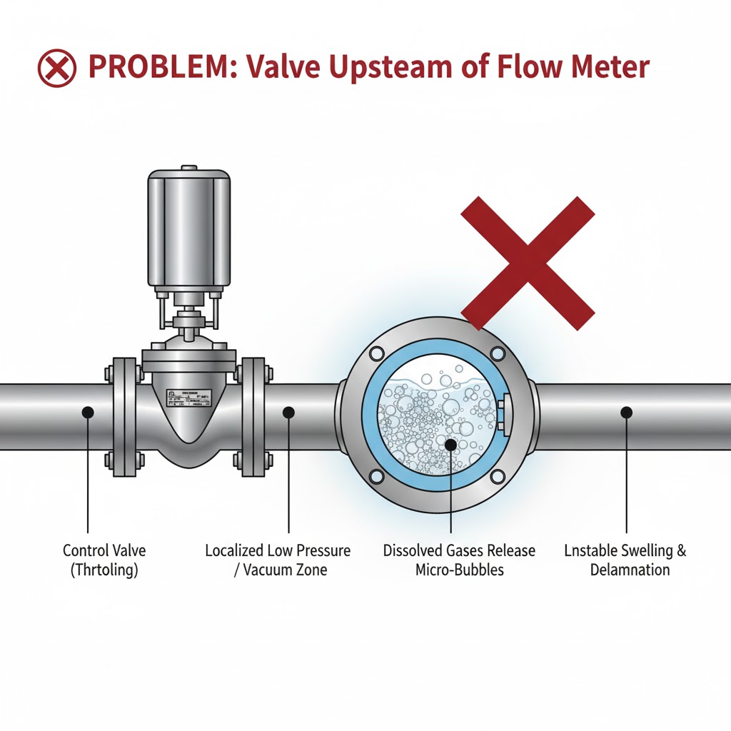
Root Cause: Negative Pressure and Gas Release
When the control valve throttled—especially at small openings or when temporarily closed—it produced a localized low-pressure or even negative-pressure zone downstream.
Inside the electromagnetic flow meter:
Dissolved gases in the fermented liquid were released due to the pressure drop.
Large quantities of micro-bubbles entered the meter tube.
This created two direct measurement errors:
1) Indicated flow becomes higher than actual flow
Because bubbles occupy volume and reduce conductive liquid content.
2) Output signal becomes noisy
Gas bubbles intermittently cover the electrodes, causing unstable conductivity and fluctuating readings.
Equipment Damage: Liner Failure
Most standard electromagnetic flow meters cannot withstand negative pressure, especially in larger diameters.
The vacuum condition caused:
Liner swelling
Bubbles between liner and tube wall
Partial detachment
Below is an example of negative-pressure tolerance for IFS4000 series sensors (values depend on medium temperature):
Excessive vacuum conditions during throttling exceed the allowable negative-pressure rating and damage the liner.
This case demonstrates a key rule:
🚫 Installing a control valve upstream may create flow conditions that are unfavorable for measurement and harmful to the flow meter itself.
2. Straight-Pipe Requirements: Another Reason to Install Flow Meters Upstream
Flow meters—especially vortex, ultrasonic, and differential-pressure types—require stable, fully developed flow profiles.
Control valves generate:
Strong turbulence
Vortices
Asymmetric velocity profiles
These disturbances directly impact accuracy.
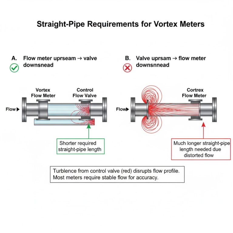
The following comparison demonstrates straight-pipe requirements for vortex meters under two different layouts:
A. Flow meter upstream → valve downstream
→ Shorter required straight-pipe length
B. Valve upstream → flow meter downstream
→ Much longer straight-pipe length needed due to distorted flow profile
The situation is similar for orifice plates and many other meter types.
This is particularly important in sites where space is limited.

3. Summary: Why Flow Meters Should Usually Be Upstream
✔ Prevent vacuum and cavitation that release gas
Especially critical for electromagnetic and ultrasonic meters.
✔ Protect flow meter components
Avoid liner damage, coating detachment, or electrode exposure.
✔ Ensure stable flow profile
Better accuracy due to reduced turbulence.
✔ Reduce straight-pipe requirements
Helps minimize installation footprint.
4. Are There Exceptions?
Yes. While the general rule is “flow meter before the valve,” certain special applications may allow or require:
Control valve installed upstream
Flow meter downstream
For example:
To maintain minimum flow velocity
To avoid zero-flow dead zones
When using special meter types with low sensitivity to turbulence
However, such cases must be evaluated carefully based on medium properties, pressure conditions, and meter specifications.
5. Final Thoughts
Understanding the interaction between flow meters and control valves is essential for achieving reliable measurement and long-term system stability. Real installation environments can be complex, and sometimes engineers must adapt layouts to specific site conditions.
Have you encountered similar issues in your projects?
How did you resolve installation conflicts between flow meters and valves?
Feel free to share your experience or reach out for technical support.