When a tank ruptures or a fire breaks out in a refinery, it’s often not the first firefighting crew that decides whether the blaze is contained—it’s the low concrete wall standing quietly around the tank.
That wall, known as a fire dike or bund wall, is the last line of defense protecting workers, the environment, and the entire facility from catastrophic loss.
1. What Is a Fire Dike (Bund Wall)?
A fire dike (also called a bund wall or retaining wall) is a closed containment structure built around tanks storing flammable, combustible, or toxic liquids.
Its main purpose is to confine leaked or spilled liquid, prevent fire spread, and minimize secondary disasters.
It functions as a passive safety device — a barrier that requires no external power or control system. Once a tank ruptures, the dike automatically performs its role: containing the liquid, isolating the fire, and preventing contamination.
Core functions include:
Contain spilled liquids within the tank area.
Prevent flames and radiant heat from spreading to nearby tanks.
Reduce the risk of explosions and boil-over events.
Provide a confined space for firefighting and emergency drainage.
In essence, it acts as a secondary containment system—the invisible “safety net” behind every tank farm.
2. Legal and Regulatory Framework
Setting up a fire dike is not a voluntary safety measure—it is a mandatory requirement in most industrial design codes.
Below are key standards that define design criteria for fire dikes and containment walls:
| Category | Code No. | Standard Name | Key Provisions |
|---|---|---|---|
| National Standard (China) | GB 50160-2018 | Code for Design of Petrochemical Enterprises | Defines dike volume, spacing, drainage, and fire protection requirements |
| Industry Standard | GB 50074-2014 | Code for Design of Oil Depots | Specifies bund capacity and compartmentalization |
| Industry Standard | GB 50351-2014 | Fire Protection Design Code for Oil and Gas Engineering | Covers explosion resistance, liquid containment, and drainage requirements |
| Safety Standard | AQ 3010-2007 | General Rules for Hazardous Chemical Storage | Regulates dike distance, inspection, and maintenance frequency |
| International Standard | NFPA 30 (U.S.) | Flammable and Combustible Liquids Code | Reference for global projects and multinational designs |
Among them, GB 50351 is particularly significant for oil and gas storage and transmission facilities.
It requires that:
Every tank area must have a containment dike.
Each dike should include emergency drainage channels and collection pits.
Dikes for high-risk liquids (e.g., condensates, liquefied gases) must be explosion-resistant and equipped with pressure relief outlets.
Dike capacity and drainage must be independent from general site drainage systems.
These requirements make the fire dike an integral part of every compliant tank farm design.
3. Design Principles and Parameters
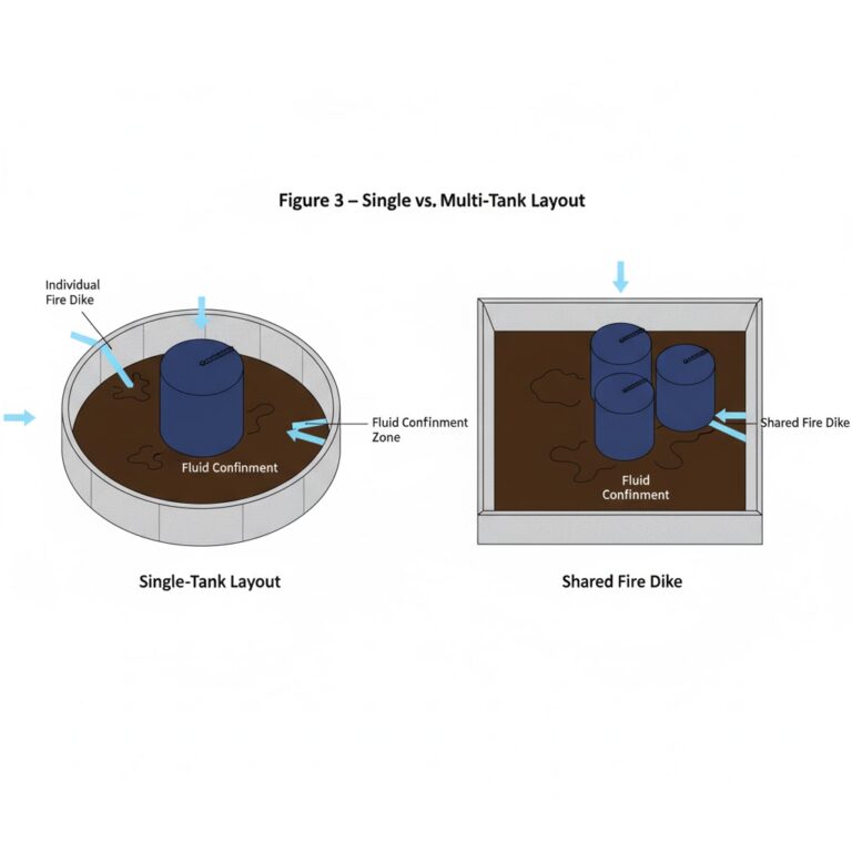
(1) Capacity and Height
Single-tank layout: Effective dike volume ≥ 110% of the largest tank’s capacity.
Multi-tank layout: Effective dike volume ≥ 33–50% of the largest tank’s capacity.
For liquefied gases: Explosion-resistant walls or alternative containment structures are preferred.
Typical height: 0.8–1.5 m depending on terrain and stored liquid properties.
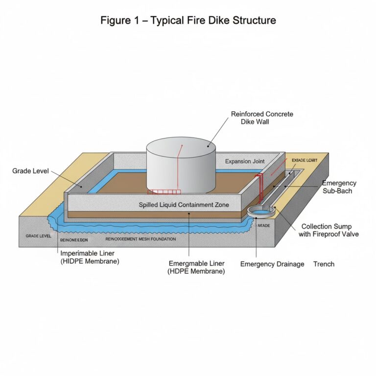
(2) Structure and Materials
Materials: Compacted clay, reinforced concrete, brick masonry, or composite impermeable layers.
Internal lining: Impermeable coating (e.g., HDPE membrane, epoxy mortar, or bituminous concrete).
Foundation: Should include reinforcement mesh and expansion joints to prevent settlement cracking.
(3) Drainage and Leak Control
Each dike must have an emergency drainage channel and a collection sump.
Drain outlets should be equipped with fireproof shutoff valves.
Direct connection of dike drainage to the plant sewer system is strictly prohibited.
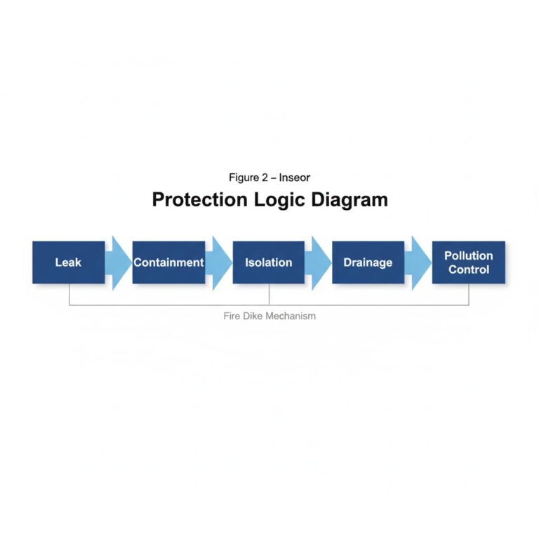
4. How Fire Dikes Work: Mechanisms of Protection
A fire dike protects the facility through four major mechanisms:
(1) Leakage Containment
If a tank bottom ruptures or a pipeline fails, the dike immediately forms a closed pool to prevent leaked liquid from flowing into the plant or nearby waterways.
(2) Fire Isolation
The dike’s height and distance create a fire separation zone, reducing heat radiation and flame spread between adjacent tanks.
(3) Explosion Mitigation
In volatile fuel storage (like LPG or condensates), a dike integrated with pressure-relief channels and blast-resistant walls can disperse the impact of vapor cloud explosions.
(4) Environmental Protection
The dike prevents contaminated liquids from infiltrating the soil or groundwater, ensuring compliance with GB 18597 – Hazardous Waste Storage Pollution Control Standard.
5. Lessons from Major Accidents
Tianjin Port Explosion (2015, China)
Investigation revealed that several storage areas lacked proper dike capacity and independent compartmentalization.
When flammable chemicals leaked, liquids overflowed into adjacent zones, triggering a chain of explosions that killed 173 people and caused massive property losses.
Refinery Crude Tank Fire (2020)
A temporary opening in the dike was not sealed after maintenance.
When oil leaked during startup, it escaped through the open ditch, igniting a neighboring tank and causing over RMB 100 million in losses.
Key takeaway:
Fire dikes are not decorative. They are the deciding factor between a controllable incident and a full-scale industrial disaster.
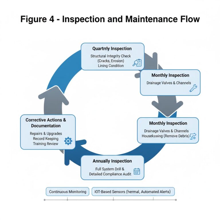
6. Maintenance and Inspection Guidelines
Like any safety barrier, fire dikes require regular inspection and maintenance.
The table below summarizes a practical inspection plan:
| Inspection Item | Frequency | Key Points |
|---|---|---|
| Structural Integrity | Quarterly | Check for cracks, settlement, erosion, or collapse |
| Impermeable Lining | Every 6 months | Inspect for corrosion, aging, or coating damage |
| Drainage Valves & Channels | Monthly | Ensure valves open/close smoothly, no blockage |
| Housekeeping | Continuous | Remove vegetation, sludge, and oil residue |
| Emergency Drill | Annually | Simulate leakage and firefighting within the dike area |
In addition, modern facilities should deploy IoT-based monitoring systems, including:
Level sensors inside containment areas.
Thermal cameras or visual monitoring.
Automated alerts for leaks, overflows, or abnormal temperature rise.
These digital tools make safety supervision proactive instead of reactive.
7. The Engineering Logic Behind Fire Dikes
A properly designed fire dike is more than a wall—it represents a philosophy of layered safety.
It assumes that even with the best controls, accidents will still happen, and systems must be ready to contain the worst outcome.
The logic can be summarized as:
Predict Failure → Design Containment → Prevent Escalation → Enable Recovery
This mindset is consistent with “Safety by Design”, a core concept of modern industrial risk management.
8. Conclusion: Safety Is Built, Not Assumed
Fire dikes stand as silent sentinels in every tank farm.
They are not glamorous or high-tech, yet when an emergency strikes, they are the first—and sometimes the only—barrier that stands between a minor incident and a national disaster.
From GB 50160 to NFPA 30, from design principles to daily inspection, fire dikes embody the most fundamental idea in industrial safety:
“Prepare for the worst, so that the worst never happens.”