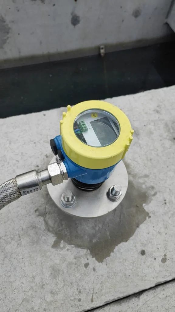
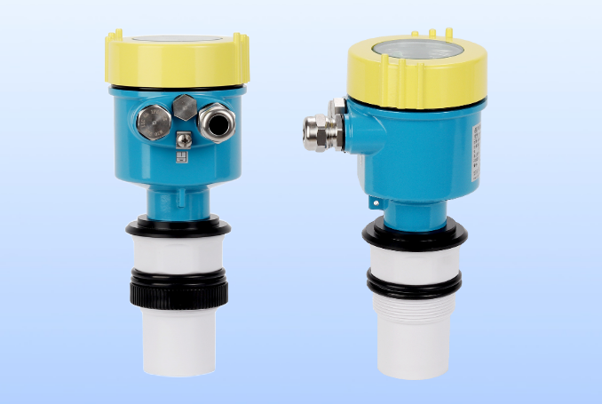
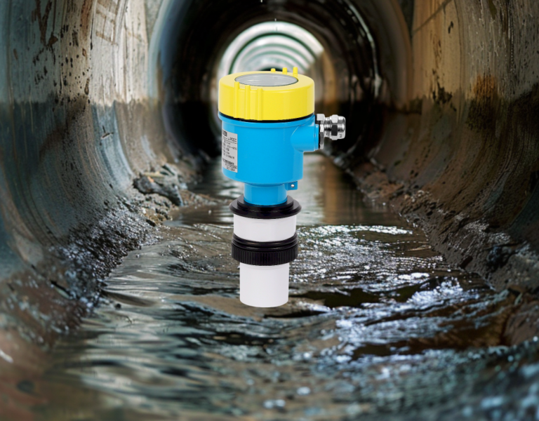
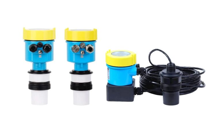
Ultrasonic level meters are widely used in industrial applications to measure the level of liquids and solids within tanks, silos, and other containers. However, these devices inherently possess blind zones, which refer to the regions where accurate measurements cannot be obtained. These blind zones typically include the area closest to the sensor probe (known as the near-field blind zone) and the distant region where signals become too weak to be detected reliably (known as the far-field blind zone). The existence of these blind zones can be attributed to several technical and environmental factors.

Key Factors Contributing to Ultrasonic Level Meter Blind Zones
1. Transmission and Reception Mechanism
Ultrasonic level meters operate by emitting ultrasonic pulses and detecting the reflected echo signals from the target surface. However, there is an inherent delay in switching from transmission to reception mode. During this transition period, the sensor is unable to detect any incoming signals, resulting in a near-field blind zone. The duration of this delay depends on the sensor design and the speed of sound in the medium.
Solutions to Mitigate Transmission-Related Blind Zones:
Use of dual transducers: One for transmitting and another for receiving to reduce the transition delay.
Optimization of pulse duration: Shorter pulses can minimize the near-field blind zone.
Improved electronic switching circuits: Faster response times can help shorten the blind zone.

2. Mechanical Design and Installation Constraints
The physical size and design of the ultrasonic sensor play a critical role in blind zone formation. If the sensor is too large or is improperly positioned in relation to the container wall or other obstacles, it may result in areas where level changes are undetectable.
Common Design-Related Causes:
Inadequate sensor positioning leading to signal interference with container walls.
Presence of obstructions such as agitators or internal structures that block signal propagation.
Inappropriate mounting angles affecting wave reflection.
Possible Solutions:
Selecting compact sensors with optimized mounting options.
Positioning the sensor at an optimal angle to minimize interference.
Using guided wave technology for better accuracy in confined spaces.
3. Signal Attenuation Over Distance
As ultrasonic waves travel through the medium (air, liquid, or solid), their intensity gradually diminishes due to factors such as dispersion and absorption. When the returning echo signal becomes too weak, it cannot be reliably detected, leading to a far-field blind zone.
Factors Affecting Signal Attenuation:
Medium properties such as temperature and humidity.
Distance between the sensor and the liquid surface.
Surface conditions that may scatter or absorb sound waves.
Mitigation Techniques:
Using higher power transducers for longer range detection.
Employing signal amplification techniques to enhance weak signals.
Utilizing echo processing algorithms to extract meaningful data from low-amplitude signals.

4. Environmental Influences
Environmental conditions can significantly impact ultrasonic wave propagation. Factors such as humidity, temperature fluctuations, steam, dust, and airborne particles can absorb, reflect, or scatter the ultrasonic waves, increasing the size of blind zones.
Environmental Factors:
High humidity causing signal dampening.
Presence of steam or foam altering the reflection characteristics.
Dust and other particulates introducing noise into the measurement system.
Possible Countermeasures:
Installing protective enclosures to shield the sensor from harsh environments.
Using compensation algorithms to adjust for temperature and humidity variations.
Regular maintenance to remove contaminants from the sensor surface.
5. Surface Reflection Characteristics
The nature of the liquid or solid surface being measured can also influence blind zones. Factors such as surface turbulence, foam formation, and irregularities can scatter or absorb ultrasonic waves, leading to measurement inaccuracies.
Common Challenges:
Liquids with high turbulence generating inconsistent reflections.
Presence of foam acting as an ultrasonic energy absorber.
Uneven surfaces causing irregular signal reflections.
Recommended Solutions:
Implementing radar-based alternatives for turbulent surfaces.
Using foam-penetrating ultrasonic technology.
Selecting sensors with adaptive signal processing for challenging surfaces.

Strategies to Minimize the Impact of Blind Zones
To enhance the accuracy and reliability of ultrasonic level measurements, the following strategies can be employed:
Sensor Selection: Choosing sensors with minimal blind zones and higher sensitivity for the specific application.
Proper Installation: Ensuring correct positioning and orientation to maximize measurement accuracy.
Regular Calibration: Periodic calibration to account for environmental and operational changes.
Advanced Signal Processing: Employing digital signal processing techniques to filter out noise and enhance weak signals.
Supplementary Technologies: Combining ultrasonic sensors with other technologies such as radar or laser-based sensors for comprehensive monitoring.
By understanding the factors contributing to blind zones and implementing the appropriate corrective measures, industries can improve the accuracy and reliability of their ultrasonic level measurement systems.
