In modern manufacturing, a feeder machine is not just an automatic conveying device but a crucial node in industrial automation systems that enables “continuous processing” and “precise control.” It determines the production line’s cycle accuracy, material utilization, and equipment coordination efficiency.
This article will delve into the working principles, drive control logic, typical structures, industry standards, selection calculations, and the intelligent development direction of feeder machines, offering a systematic reference for engineers and equipment buyers.
I. Core Working Principle of Feeder Machines
The main task of a feeder machine is to accurately deliver raw materials (coil, sheet, wire, or granular materials) to the processing position with a set step size, speed, and time, achieving synchronized, repetitive, and controllable material transport.
The essence of feeding is “displacement and cycle control,” with the core technical paths including:
Motion Control Module: Driven by servo motors or pneumatic components, achieving precise step control through position feedback (encoder).
Synchronization Signal Interface: Coordinating with presses, lasers, welders, etc., to ensure the feeding cycle synchronizes with the host machine’s operation.
Pressure and Friction Control: Ensuring proper friction in feed rollers, pressing rollers, and guide systems to prevent slipping and damage.
Tension and Material Compensation System: In coil feeding, the tension control system of the uncoiler ensures continuous and stable feeding.
Typical Feeding Formula:
Feeding Displacement = Motor Speed × Roller Diameter × Time / Reduction Ratio
In servo feeding systems, this process is automatically calculated via PLC, achieving control accuracy up to 0.01mm.
II. Structure and Control Logic of Feeder Machines
A modern feeder machine typically consists of the following core components:
Drive Mechanism: Includes spindle, synchronous belt, gearbox, and feeding rollers.
Control System: Utilizes PLC or motion control cards for parameter settings via human-machine interface (HMI).
Detection System: Configures photoelectric sensors or encoders for position feedback.
Clamping Device: Common types include pneumatic clamps or roller pressing mechanisms.
Base and Guide Rail System: Ensures mechanical stability and linear accuracy.
Control Logic:
Mold Signal Trigger → Control System Sends Feeding Command → Drive Motor Rotates → Material Advances → Position Detection Feedback → Wait for Press Signal → Enter Next Cycle.
This closed-loop control process guarantees synchronization, stability, and repeatability of the feeder machine.
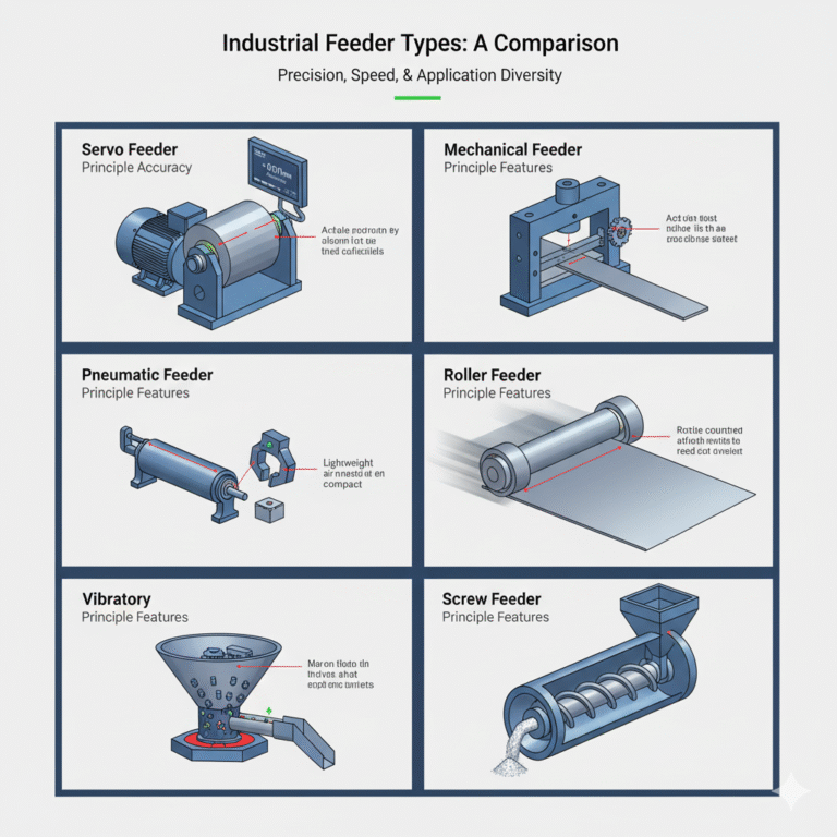
III. Comparison of Technical Features Across Different Feeder Types
| Type | Drive Principle | Feeding Accuracy | Applicable Thickness | Characteristics | Applications |
|---|---|---|---|---|---|
| Mechanical Feeder | Linkage or eccentric wheel | ±0.2mm | ≤2.5mm | Strong synchronization with presses, simple structure | Medium and low-speed stamping lines |
| Pneumatic Feeder | Pneumatic cylinder | ±0.3mm | ≤1.5mm | Low cost, easy maintenance | Small parts stamping, light load |
| Servo Feeder (NC Feeder) | Servo motor + PLC control | ±0.01mm | ≤6.0mm | High-speed, high precision, programmable control | Precision electronics, automotive stamping |
| Roller Feeder | Double roller friction drive | ±0.1mm | ≤4.0mm | Smooth operation, high speed | High-speed continuous die stamping |
| Vibratory Feeder | Electromagnetic vibration | ±0.5mm | Small parts | Suitable for bulk materials and powders | Electronics, pharmaceuticals, packaging |
| Screw Feeder | Screw conveyor | ±2mm | Powder/Granular | Can achieve metered control | Food, plastics, chemicals |
Trend Analysis:
Currently, servo feeders, with their “flexible control + high-precision positioning” advantages, are gradually replacing traditional pneumatic and mechanical feeders, becoming the mainstream solution for stamping automation.
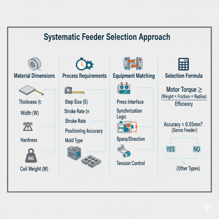
IV. Systematic Feeder Selection Approach
Feeder selection is not simply about choosing a model; it’s a system matching process, requiring coordination with host machines, molds, materials, and cycle parameters.
Material Dimensions:
Thickness (t): Determines roller pressure and motor torque.
Width (W): Affects roller length and guiding structure.
Material Hardness: Determines friction coefficient and anti-slip design.
Coil Weight (M): Affects feeding force and inertia compensation.
Process Dimensions:
Step Size (S): Set according to the mold spacing.
Stroke Rate (n): Number of strokes per minute.
Positioning Accuracy: Typically choose servo feeding for accuracy within 0.05mm.
Mold Type: Single station/multi-station molds.
Equipment Matching Dimensions:
Press Output Signal Interface: (e.g., 1P, 2P triggering modes).
Synchronization Control Method: PLC or mechanical linkage.
Space Constraints and Feeding Direction.
Tension Control Strategy in Collaboration with Uncoilers and Levelers.
Selection Experience Formula:
Motor Torque ≥ (Material Weight × Friction Coefficient × Roller Radius) / Efficiency Factor.
V. Industry Standards and Performance Evaluation Indicators
Common standards include:
GB/T 5226.1-2019: Machinery safety and electrical control systems.
JIS B 6060: Feeder machine specifications for metal sheet feeding.
ISO 230-2:2014: Methods for measuring machine tool motion accuracy.
Evaluation indicators primarily include:
Feeding accuracy (mm)
Maximum feeding speed (m/min)
Programmable step size range (mm)
Repeatability and stability (Cpk ≥ 1.67)
Motor response time and synchronization lag compensation ability
VI. Typical Industry Application Cases
Automotive Stamping Lines: Large steel coils are fed into molds by NC servo feeders in sync with CCD vision systems for automatic scrap removal.
Electronics Manufacturing: Precision feeders are used for FPC and connector stamping, with feeding errors controlled within ±0.01mm.
New Energy Battery Industry: Dual-servo drive feeding systems are used for continuous copper foil feeding and tension control.
Metal Sheet Welding Lines: Multi-axis feeding systems achieve parallel synchronous feeding across multiple lines, increasing production speed by 30%.
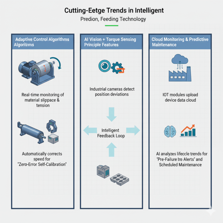
VII. Cutting-Edge Trends in Intelligent Feeding Technology
The intelligent development of feeders is mainly reflected in three areas:
Adaptive Control Algorithms: Real-time monitoring of material slippage and tension, automatically correcting speed curves for “zero-error self-calibration.”
AI Vision + Torque Sensing: Using industrial cameras to detect position deviations, torque sensors to assess friction status, forming an intelligent feedback loop.
Cloud Monitoring and Predictive Maintenance: IoT modules upload device data, with AI analyzing lifecycle trends for “pre-failure alerts” and “scheduled maintenance.”
VIII. Conclusion
Feeder machines have evolved from simple mechanical devices to intelligent equipment with data interaction, smart sensing, and high-precision control.
In the future, feeder systems will no longer be just “transportation mechanisms” but “digital twin units” with learning capabilities, network connectivity, and predictive maintenance. When selecting a feeder, enterprises should not only focus on “whether it can feed” but also on “feeding steadily, feeding accurately, and feeding intelligently.”