In industrial plants, energy metering systems, and water or wastewater applications, inaccurate flow readings are a common complaint.
Very often, the first assumption is that the flow meter itself is faulty or poorly selected.
However, real field experience shows a different truth:
In most cases, inaccurate flow measurement is caused by improper installation and unfavorable process conditions — not by the instrument itself.
It is not unusual to see a flow meter perform accurately during factory testing or calibration, yet display large errors once installed on site. Even the most accurate instrument cannot deliver reliable results if the flow profile is distorted, the pipe is not fully filled, grounding is incorrect, or electrical noise interferes with the signal.
This article summarizes the most critical installation principles, common pitfalls, and practical field checks that can immediately improve flow measurement reliability.

1. Key Concepts Every Flow Measurement Engineer Should Know
Straight Pipe Length
Flow meters require a section of straight, unobstructed pipe upstream and downstream to establish a stable velocity profile.
Disturbances caused by elbows, valves, tees, reducers, pump outlets, or heat exchangers introduce swirl, asymmetry, and secondary flows, which lead to systematic measurement errors and unstable readings.
Pipe Diameter (D)
“D” refers to the internal diameter of the pipe.
For example, 10D upstream means a straight pipe length equal to ten times the pipe’s internal diameter before the flow meter.
Full Pipe Condition
For liquid applications, the measuring section must remain completely filled at all times.
Partially filled pipes, trapped air pockets, or two-phase flow conditions can cause severe errors or total measurement failure for electromagnetic, ultrasonic, and differential pressure flow meters.
Back Pressure
Adequate downstream back pressure helps:
Prevent gas release and flashing
Maintain a full pipe condition
Reduce cavitation and flow instability
Low back pressure, especially near open discharge points or high pipe elevations, often leads to air entrainment and unstable readings.
Grounding and Shielding
Many flow meters operate with very low signal levels.
For example, electromagnetic flow meters typically measure electrode signals in the millivolt range. Improper grounding, shielding, or cable routing allows electromagnetic interference from VFDs, motors, and relays to corrupt the signal, resulting in drift, noise, or zero instability.

2. Installation Location Check — Before Mounting the Meter
Finding a place where a meter can be installed is not the same as finding a place where it will measure accurately.
Before installation, engineers should quickly verify:
Process Conditions
Is the medium liquid, gas, steam, slurry, or multiphase?
Are temperature and pressure conditions stable?
Is there a risk of degassing, flashing, or condensation?
Are there sources of air, bubbles, or solids upstream?
Pipe Layout
Is sufficient straight pipe available?
Will the pipe remain fully filled during all operating modes?
Is the location close to strong electrical interference sources?
Is the meter installed near a pump suction, discharge, or control valve?
In many cases, choosing the correct installation location costs nothing, while correcting a poor location later can be expensive and time-consuming.

3. Managing Flow Disturbances
Any component that changes flow direction or velocity profile introduces disturbance:
Elbows
Control valves
Tees
Reducers / expanders
Pump and compressor outlets
General field recommendations:
Keep major disturbances as far upstream as possible
Avoid sudden throttling immediately downstream
Place control valves downstream of the meter when possible
Typical straight pipe guidelines:
| Flow Meter Type | Upstream | Downstream |
|---|---|---|
| Electromagnetic | ≥ 5D | ≥ 3D |
| Vortex / Ultrasonic | ≥ 10D | ≥ 5D |
| Orifice / Nozzle (DP) | ≥ 20D (typical) | ≥ 5D |
Longer straight runs are recommended when strong disturbances are unavoidable.

4. Common Installation Mistakes
High-Risk Locations
Pipe high points where air accumulates
Free discharge or open outlet lines with insufficient back pressure
Downhill sections where siphoning or negative pressure may occur
Locations immediately after control valves or pumps
Preferred Locations
Vertical pipes with upward flow
Horizontal pipes installed at low points
Bottom sections of U-shaped pipe layouts
Quick Field Checks
Does the pipe ever run partially empty during start/stop?
Is the downstream pressure close to atmospheric?
Are air vents or drains installed where needed?
Typical Remedies
Install a back pressure valve
Add air release valves at high points
Relocate the meter to a vertical upward flow section

5. Electromagnetic Flow Meter Installation Essentials
Electromagnetic flow meters rely on induced voltage generated by conductive liquids moving through a magnetic field.
This makes them highly sensitive to full pipe conditions and electrical integrity.
Best practices:
Ensure the pipe remains completely full
Avoid installation at high points or near open discharge
Position electrodes to minimize sediment buildup and gas exposure
Use proper grounding rings or electrodes for non-metallic pipes
Follow manufacturer grounding and shielding instructions
Route signal cables separately from power and VFD cables
Typical symptoms of installation issues:
Flow reading does not return to zero at no flow
Readings fluctuate with VFD frequency changes
Large transient spikes during equipment start/stop
In such cases, installation conditions should be checked before suspecting instrument failure.
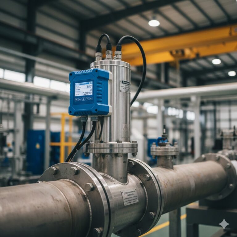
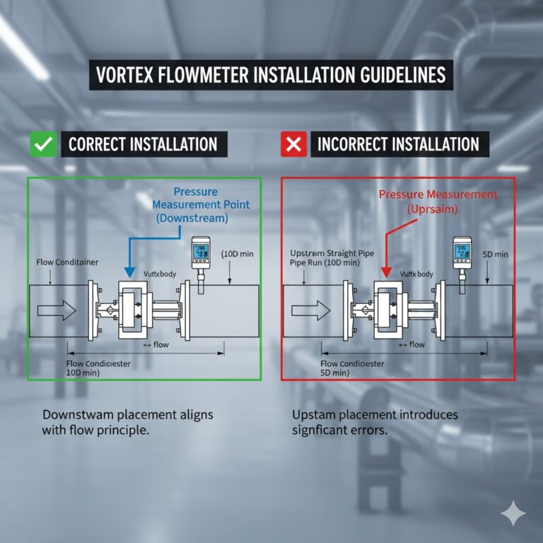
6. Vortex Flow Meter Installation Considerations
Vortex flow meters measure flow based on vortex shedding frequency.
They are particularly sensitive to vibration and unstable flow conditions.
Key points:
Avoid mounting on vibrating pipe sections
Keep distance from compressors, pumps, and unsupported piping
Place control valves downstream
For steam applications, ensure proper insulation and condensate management
Prevent two-phase flow for gas and steam services
When readings fluctuate, mechanical vibration and phase changes should be investigated first.
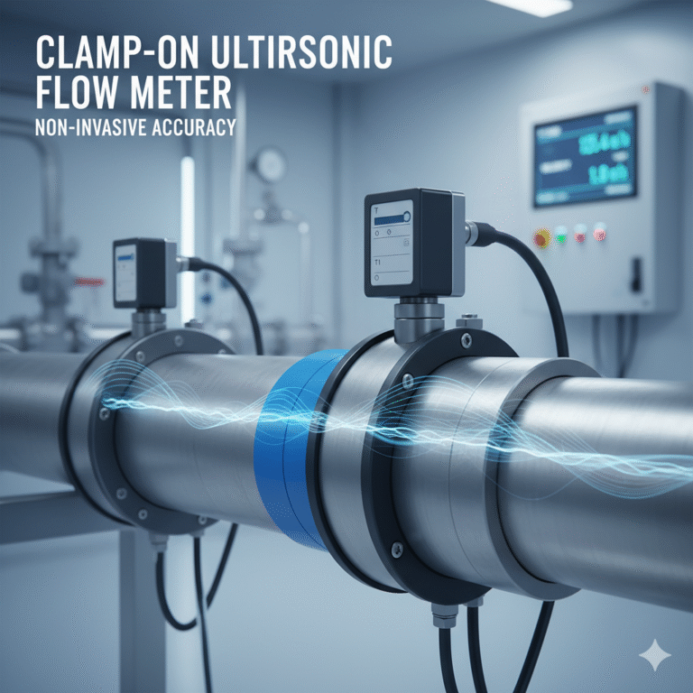
7. Ultrasonic Flow Meter Installation Tips
Clamp-on ultrasonic flow meters offer non-intrusive installation, but accuracy strongly depends on installation quality.
Critical factors:
Clean, smooth pipe surface
Avoid weld seams, corrosion, and thick coatings
Proper coupling gel application
Accurate input of pipe material, diameter, wall thickness, and lining
Verification of signal strength and quality indicators
Incorrect parameters result in incorrect calculations — even if the instrument itself is functioning perfectly.
8. Commissioning and Acceptance Checks
Before accepting flow measurement results:
Verify flow direction and signal mapping
Perform zero checks under no-flow conditions if possible
Analyze trends instead of single readings
Cross-check mass or volume balance within the system
Confirm logical consistency between multiple measurement points
These steps often reveal installation or configuration issues immediately.

9. Conclusion
Flow measurement accuracy is rarely achieved by purchasing a high-end instrument alone.
Accurate flow measurement is engineered — not bought.
By ensuring proper straight pipe lengths, full pipe conditions, correct grounding, vibration control, and accurate parameter settings, flow meters deliver stable and trustworthy data that supports safe operation, process optimization, and energy management.