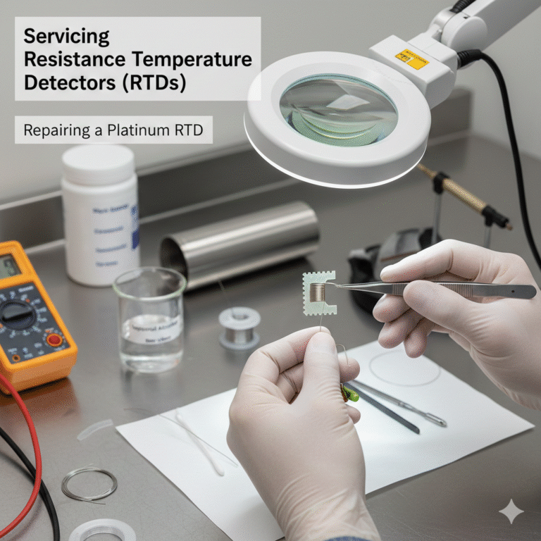
Introduction to Armored Resistance Thermometers
Armored resistance thermometers are a combination of a metal protective tube, insulation material, and a resistance element. Typically, the resistance element is made of platinum wire (though nickel wire is also used), and the insulation material is magnesium oxide powder. The protective tube is commonly made of stainless steel. These thermometers are available in various sizes, such as ∅5, ∅6, and ∅8, with lengths ranging from 10 to 1000mm.
Key Characteristics of Armored Resistance Thermometers:
Low thermal inertia: They respond quickly to temperature changes.
Flexibility: Ideal for use in complex or confined spaces.
Vibration and shock resistance: Suitable for environments with high mechanical stress.
Long lifespan: The resistance element is well protected by insulation and a tightly sealed protective tube, preventing oxidation.
Introduction to Semiconductor Point Thermometers
Semiconductor point thermometers are a type of resistance thermometer, typically designed as portable devices. These thermometers use semiconductor thermistors, coupled with highly sensitive microammeters, to measure the temperature at a specific point or surface that is rapidly changing.
Advantages of Semiconductor Point Thermometers:
Simple manufacturing process and low cost.
High sensitivity with a large negative temperature coefficient (resistance decreases as temperature increases).
Fast response due to the small size of the thermistor (diameter: 0.2 to 0.5mm).
However, semiconductor thermistors have some limitations:
Narrow temperature range.
Non-linear resistance-temperature relationship.
Manufacturing process is difficult to control, leading to poor interchangeability.
What to Consider When Servicing RTD Temperature Sensors
Cleaning the Protective Tube:
When removing the RTD temperature sensor from its protective tube, ensure that any rust or oil residues inside the tube are cleaned thoroughly.Handling the Resistance Element:
Platinum Resistance: Avoid touching the platinum wire directly and do not disassemble it.
Copper Resistance: Do not remove the enamel coating from the copper wire.
Adjusting the Resistance at 0°C (R0):
Adjust the R0 value at the end of the sensor.
If R0 is too small, copper resistance can be increased by welding the same gauge enamel-coated wire.
For platinum resistance, gently pull the wire using tweezers to increase the value.
Extending the Lead Wires:
If the lead wires are too short when reinstalling the sensor into the protective tube, extend them as follows:
Use copper wires of the same gauge for copper resistance.
For platinum resistance, use silver wires of the same gauge (arc weld using a 12V voltage).
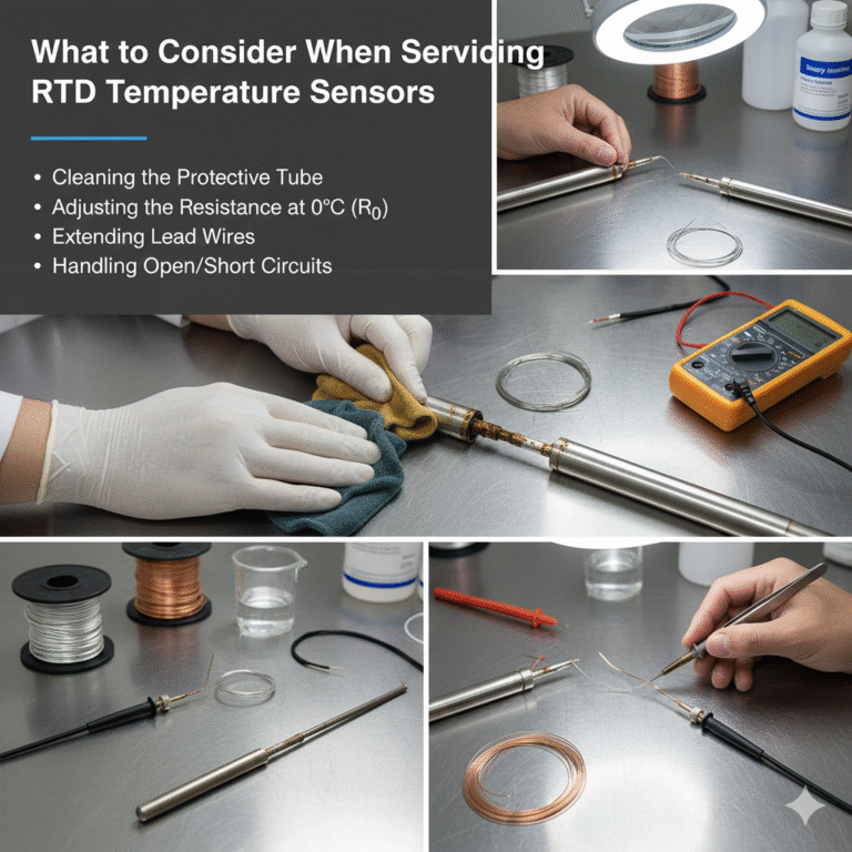
Handling Copper RTDs with Open Circuit or Short Circuit
Open Circuit:
If the enamel coating on the copper resistance wire is stripped and green rust is present, the sensor is damaged and should be discarded. If only a small portion of the coating is missing, it can be repaired:
Locate the damaged wire section and remove the coil up to the broken point.
Use a soldering iron to repair the wire, ensuring continuity.
Rewind the wire neatly and apply varnish insulation to the soldering joint.
Dip the entire element in varnish and dry it in an oven.
Short Circuit:
Moisture or damaged insulation can cause short circuits. If the element is wet, dry it in an oven at 80-100°C for 1-2 hours.
If the short circuit is caused by insulation damage, remove the damaged section, re-insulate with varnish, and re-coil the wire.

Handling Platinum RTDs with Open Circuit or Short Circuit
Open Circuit:
For commonly used platinum RTDs with mica, glass, or ceramic frames, only those with a mica frame can be repaired. Follow these steps:
Remove the insulation ceramic beads securing the frame and rotate them 90° to expose the platinum wire wound on the sawtooth-shaped mica frame.
Use a magnifying glass to inspect the break in the platinum wire.
If the break is between the platinum wires, arc-weld using a 6V voltage. If it’s between the platinum wire and the lead wire, use a 10V arc weld.
Short Circuit:
Short circuits occur if the mica insulation is damaged or if the platinum wires are loose and touching each other. Use tweezers to separate the wires.
Final Check:
After repairing the open or short circuit, verify the resistance value at 0°C (R0) to ensure proper functionality.