In modern industrial systems, Distributed Control Systems (DCS) are widely used to monitor and control motor operation in real-time. One common issue that often arises during operation is a mismatch between the DCS feedback current and the actual motor current. This discrepancy, if not addressed properly, may result in control errors, false alarms, or even equipment failure.
In this article, we’ll explore the possible causes of such inconsistencies and offer a structured troubleshooting approach.
🔍 Understanding the Problem
The problem usually surfaces in one of the following forms:
DCS screen shows a current value that is significantly different from the value measured on-site.
The mismatch is either constant or fluctuates with load.
Operators report erratic or unstable motor performance related to current feedback.
🧭 Possible Causes and Troubleshooting Methods
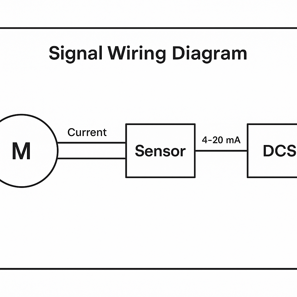
1. Signal Type or Range Mismatch
If the sensor output is 4–20 mA but the DCS input is configured for 0–10 V, the readings will be inaccurate.
✅ Solution:
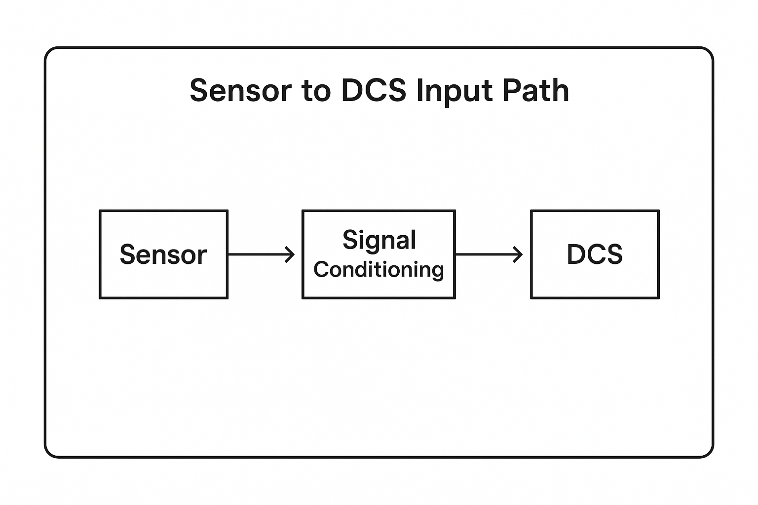
Verify that the output signal type (current or voltage) from the transducer matches the input configuration of the DCS analog input (AI) module.
Check that both systems use the same measurement range (e.g., 0–100 A = 4–20 mA).
2. Sensor or Transducer Fault
A worn-out or faulty current sensor (e.g., current transformer, Hall effect sensor) may output a drifting or fixed value.
✅ Solution:
Replace the sensor and compare readings before and after.
Use a portable clamp meter to check the actual motor current and cross-check it with the sensor output.
3. Wiring or Terminal Issues
Loose terminals, broken signal wires, or improper cable shielding can cause signal degradation or loss.
✅ Solution:
Inspect terminals and tighten if necessary.
Ensure the analog signal cables are free from moisture, damage, or electromagnetic interference (EMI).
Re-crimp or replace cables if necessary.
4. DCS Analog Input Module Malfunction
The analog input module in the DCS may suffer from channel faults, zero drift, or low precision.
✅ Solution:
Test the analog input module using a signal simulator (e.g., 4–20 mA source).
Replace or recalibrate the AI module if discrepancies persist.
5. Ground Loop or Electrical Interference
Improper grounding or signal loop problems can introduce noise or incorrect readings.
✅ Solution:
Ensure proper single-point grounding of signal cables.
Avoid sharing power supply and signal wiring paths.
Install signal isolators if needed.
6. Configuration or Display Errors
Sometimes, the error is not physical but logical—incorrect scaling, unit settings, or HMI display parameters may cause confusion.
✅ Solution:
Check DCS engineering configuration, including scaling coefficients, display units (A vs. mA), and signal conversion logic.
📋 Recommended Step-by-Step Diagnosis
Step
Action
Tool
1
Measure actual motor current
Clamp meter
2
Simulate 4–20 mA signal to DCS input
Current signal generator
3
Visually inspect and test cable continuity
Multimeter
4
Check DCS trend data for stability or drift
DCS trending tool
5
Swap input channels to identify module faults
Spare AI channel/module
🔧 Interim Compensation (If Immediate Fix Not Possible)
If hardware replacement is not immediately feasible, a temporary compensation can be applied in the DCS configuration:
Add a linear correction factor or bias offset in the signal scaling block.
Clearly label the correction in documentation for future traceability.
🧠 Conclusion
A mismatch between DCS feedback current and actual motor current can stem from multiple sources—from hardware failure to configuration errors. A structured approach involving verification, calibration, and comparison is key to resolving the issue efficiently.
Always remember:
“Trust, but verify”—never fully trust what the screen shows without confirming the actual value at the field level.
If you’d like help diagnosing a specific case or integrating accurate motor current monitoring into your DCS system, feel free to contact our engineering team.