1. Working Principle of a Centrifugal Pump
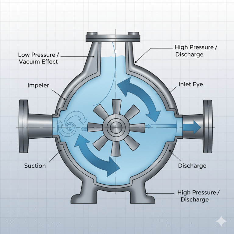
Before starting, the centrifugal pump must first be filled with liquid. When the impeller rotates, the liquid is subjected to centrifugal force and is thrown towards the outer edge of the impeller. This imparts kinetic energy to the liquid, which is then discharged through the outlet. Meanwhile, the pressure in the center of the impeller drops, creating a vacuum effect, and the surrounding liquid is drawn in from the outside by atmospheric pressure. This process continues as a cycle of “suction, pressurization, and discharge.”
In brief: Impeller rotates → Creates a vacuum → Liquid is drawn in and pressurized.
2. Formation Mechanism of Cavitation
Cavitation occurs when the pressure at a certain point in the pump (such as at the impeller inlet, P₁) drops below the vapor pressure of the liquid, causing the liquid to vaporize rapidly and form vapor bubbles. As these bubbles move into the high-pressure zone, they implode, producing intense liquid impacts. The cavitation process involves:
The local pressure drops below the saturation vapor pressure.
Vapor bubbles form and travel with the flow.
Upon entering the high-pressure area, the bubbles collapse, creating micro-vacuums.
The surrounding liquid moves at high speed, causing high-frequency pressure shocks.
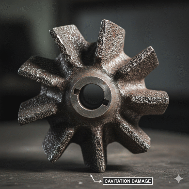
This results in erosion of the impeller surfaces, which may appear as pitting, grooving, or honeycomb damage, and is often accompanied by intense vibration and noise.
3. Dangers of Cavitation
Cavitation causes significant noise and vibration, and it can lead to mechanical fatigue and chemical corrosion of metal surfaces. The sudden collapse of bubbles generates pressures of several hundred megapascals, which strike the metal surfaces, causing the impeller surface to erode. The release of heat during vapor condensation accelerates oxidation, further contributing to metal corrosion.
Commonly damaged parts include:
The impeller’s inlet and outlet edges
The pump casing inlet
The wear surfaces of guide vanes and volutes
In the early stages, pitting may appear, which can later develop into grooves, honeycomb cavities, and, in severe cases, lead to perforation or fracture of the impeller.
4. Relationship Between Saturation Vapor Pressure and Cavitation
Saturation vapor pressure refers to the pressure at which liquid and vapor are in equilibrium. The higher the temperature, the greater the saturation vapor pressure. For example, at 100°C, the saturation vapor pressure of water is 101.3 kPa (one atmospheric pressure). At 20°C, water can vaporize at just 2.3 kPa.
Thus, the lower the pressure, the easier it is for the liquid to vaporize. This is why cavitation is most likely to occur at the inlet of the impeller, where the pressure is lowest.
5. NPSH – A Critical Parameter
In centrifugal pumps, determining the occurrence of cavitation depends on comparing the effective NPSH (NPSHa) and the required NPSH (NPSHr).
Effective NPSH (NPSHa)
The formula for NPSHa is:Where:
: Vapor pressure at the liquid surface
: Height of the liquid column
: Losses in the suction pipe
: Saturation vapor pressure of the liquid
Typical NPSHa for common centrifugal pumps is around 8.3 meters. If NPSHa is too low, cavitation may occur.
Required NPSH (NPSHr)
NPSHr is the minimum suction head required to avoid a drop in head or cavitation at a given flow rate. It is determined experimentally by gradually reducing the inlet pressure during tests. When the pump head drops by 3% or cavitation noises are clearly heard, the corresponding NPSHr is recorded.NPSHr is a fixed characteristic of the pump and is provided by the manufacturer. Different pump models can have significantly different values.
Safety Limit for Inlet Pressure
In actual operation, cavitation generally does not occur as long as the inlet pressure is no lower than -0.05 MPa (approximately 96 kPa absolute pressure) and the system is filled with liquid. If the vacuum pressure exceeds this limit, the liquid is likely to vaporize, forming bubbles.
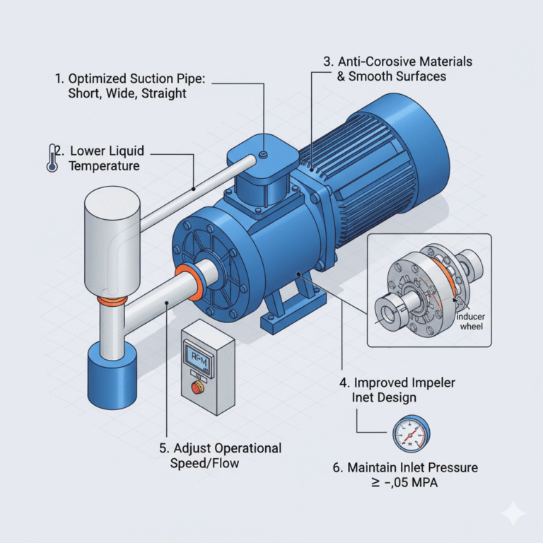
6. Measures to Prevent Cavitation
Lowering the liquid temperature: Reduces the saturation vapor pressure.
Reducing the suction height: Increases inlet pressure.
Optimizing the suction pipeline: Use smooth, short, and large-diameter pipes to minimize local losses.
Adjusting operational conditions: Reduce the pump speed or flow to prevent overload.
Increasing cavitation resistance:
Improve the impeller inlet design (increase inlet diameter, optimize blade curvature, or add inducer wheels).
Use anti-corrosive materials (such as aluminum-bronze, stainless steel, high-nickel chromium alloys, or rare-earth cast iron).
Keep the impeller surface smooth to avoid turbulence and erosion.
7. Summary and Practical Recommendations
Cavitation is a common but highly damaging phenomenon in centrifugal pumps, caused primarily by the local pressure at the inlet falling below the liquid’s saturation vapor pressure. To prevent cavitation:
Optimize the design: Focus on improving the impeller inlet.
Ensure safe operation: Keep inlet pressure ≥ -0.05 MPa (under full liquid conditions).
Ensure parameter matching: Always maintain NPSHa > NPSHr + safety margin.
Use reliable materials: Choose high-corrosion-resistant metals and maintain smooth surfaces.
Two core principles to remember:
NPSHa > NPSHr + 0.5–1 meter.
Inlet pressure ≥ -0.05 MPa (full liquid conditions).
By following these guidelines, cavitation can be effectively controlled.