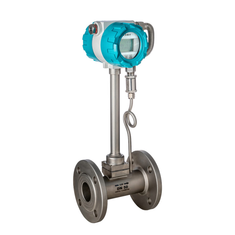
Vortex flowmeters are commonly used in laboratory and industrial applications to measure the flow rate of gases or liquids. Accurate calibration and testing are essential to ensure reliable operation and data integrity. This document outlines the three primary methods for testing vortex flowmeters: dynamic testing, static testing, and simulated signal testing.
1. Dynamic Testing (With Input Signal)
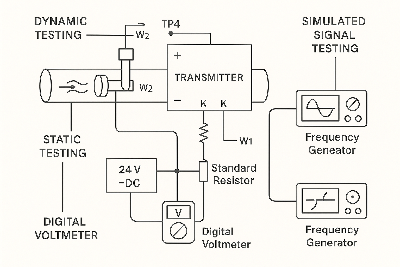
Dynamic testing is performed by simulating flow conditions and checking the output response of the transmitter.
Procedure:
Apply a full-scale input flow signal.
The signal should produce a frequency output at TP4 of approximately 1000 Hz.
The frequency-to-current converter circuit should then output a full-scale current of 20 mA DC.
If deviation is observed, adjust the W2 potentiometer to calibrate the output to 20 mA.
Note:
In most applications, adjusting the flow range does not require recalibrating W2. Instead, update the KB value on the encoding switch according to the desired range.
2. Static Testing (Without Input Signal)
Static testing checks the transmitter’s output at zero flow (no signal input).
Procedure:
Connect a 24V DC power supply in series with a standard resistor.
Measure the voltage using a digital multimeter or verify using an on-site indicator.
With no flow signal input, the current output should be 4 mA, indicating 0% flow on the display.
Adjustment:
If the current deviates from 4 mA, adjust the W1 potentiometer.
Ensure there is no input frequency signal before adjustment (use an oscilloscope or frequency counter).
If the coefficient board is disconnected, W1 can be directly used for zero adjustment.
3. Simulated Signal Testing
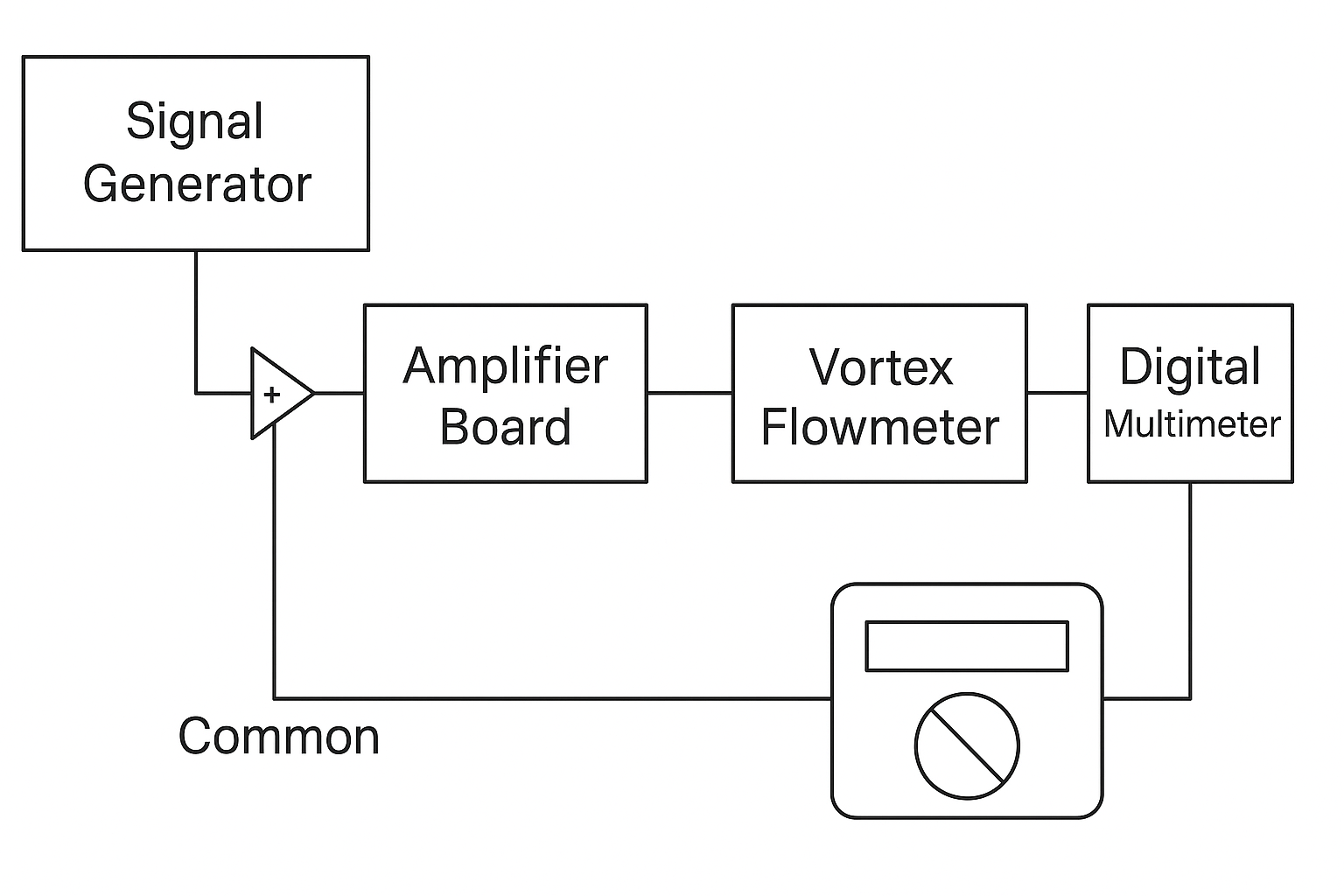
This method uses an external signal generator to simulate the probe signal and evaluate the electronic circuit’s response.
Procedure:
Replace the flow sensor signal with a frequency generator.
Connect the generator’s shield to the common ground terminal.
Connect the signal output to any input terminal on the amplifier board.
Adjust the frequency within the flowmeter’s rated range (as per its factory certificate).
Typical signal amplitude: 1–2 Vpp (may increase slightly at higher frequencies).
Purpose:
To test the response of the transmitter’s circuitry under known simulated conditions.
4. Post-Test Requirements
After testing is complete, the vortex flowmeter must be returned to its original position and stored securely.
Instrumentation supervisors should conduct regular inspections to ensure the device remains in good working condition and free from faults.
5. Notes and Recommendations
Always refer to applicable calibration standards (e.g., JJG 1030-2007, or corresponding international standards).
Ensure calibration is performed by qualified personnel using traceable reference instruments.
Maintain a detailed calibration record for compliance and traceability.