Metering performance requirements
Accuracy level
Table 2-4 is the accuracy grade series of the vortex flowmeter. The accuracy grade should be clearly indicated on the flowmeter product manual and the nameplate of the flowmeter.
| Level of accuracy | 0.5 | 1 | 1.5 | 2 | 2.5 | |
| Maximum allowable error |
qt≤q≤qmax | ±0.5% | ±1.0% | ±1.5% | ±2.0% | ±2.5% |
| qmin≤q≤qt | ±1.0% | ±2.0% | ±3.0% | ±3.0% | ±5% | |
Repeatability
The repeatability of the flowmeter shall not exceed 1/3 of the absolute value of the maximum allowable error specified by the corresponding accuracy level.
General technical requirements
1. Random files
The flow meter should have an instruction manual. The instruction manual should give the name, model, manufacturing unit, measuring medium, working pressure range, working temperature range, applicable caliber, flow range, boundary flow (when the flowmeter has this indication), accuracy level, and manufacturing measuring instrument license Serial number, explosion-proof grade and explosion-proof certificate number (used in flammable and explosive occasions), protection grade, etc. The flowmeter for subsequent verification is recommended to carry the previous verification certificate
2. Logo and nameplate
The flowmeter housing should have a clear flow direction mark. The flow meter should have a nameplate. The nameplate should generally indicate the name, model, factory number, use medium, flow range, caliber, accuracy grade, maximum working pressure, manufacturer and date of manufacture, and other technical requirements.
3. Appearance
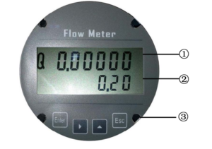
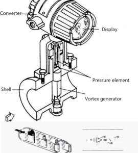
The newly manufactured flowmeter should have a good surface treatment, free of burrs, scratches, cracks, rust, mildew, and peeling of the coating. The sealing surface should be flat and free from damage. The welding of the flowmeter casing and the vortex generator should be smooth and clean, and there should be no false welding or desoldering. The flowmeter connector must be firm and reliable, and not lose or fall off due to vibration. The numbers displayed by the flowmeter should be eye-catching and tidy, and the text symbols and logos indicating the functions should be complete, clear, and correct. The buttons of the flowmeter should feel moderately without adhesion. The indicators of the flowmeter are correct; the protective glass on which the flowmeter displays numbers should have good transparency, and there should be no defects that interfere with the display such as distortion of the reading.
4. Protection function
The flow meter should have a K factor or flowmeter factor protection function, and permanent traces should be left after modification. The value of the K factor of the flow meter or the flow meter factor should be the same as the value set in the last verification.
5. Tightness
Pass the verification medium to the maximum experimental pressure, which lasts for 5 minutes, and there should be no leakage at all interfaces on the flowmeter housing
Control of measuring instruments The verification of the vortex flowmeter shall include the first verification, subsequent verification, and in-use verification.
1. Verification conditions (1) Requirements for flow standard devices The flow standard device (hereinafter referred to as the device) and its supporting instruments should have a valid verification (or calibration or test) certificate. The expanded uncertainty of the device (k=2) should not be greater than 1/2 of the absolute value of the maximum allowable error of the flowmeter to be inspected.
When the vapor pressure of the liquid used for verification is higher than the atmospheric pressure of the environment, the device should be closed. When the temperature of the fluid flowing through the flowmeter needs to be measured, the temperature can be measured directly from the temperature measuring hole on the flowmeter housing. If there is no temperature measuring hole on the flowmeter housing, the temperature measurement position should be determined according to the requirements of the flowmeter itself and related regulations. If there is no special requirement, the temperature measurement position should be set at D (2~5) downstream of the flowmeter (D is the pipe diameter, the same below). The influence of the measurement error of the thermometer used on the verification result should be less than 1/5 of the absolute value of the maximum allowable error of the flowmeter.
When it is necessary to measure the pressure of the fluid flowing through the flowmeter, the pressure can be taken directly from the pressure-taking hole on the flowmeter housing. If there is no pressure hole on the flowmeter housing, the pressure measurement position should be determined according to the requirements of the flowmeter itself. If there is no special requirement, the device should install a pressure gauge on the downstream side (2 ~ 7) D of the flowmeter. The axis of the pressure tapping hole should be perpendicular to the axis of the measuring tube, with a diameter of (4-12) mm. The influence of the measurement error of the pressure gauge used on the verification result should be less than 1/5 of the absolute value of the maximum allowable error of the flowmeter
(2) General requirements for fluids for verification ① The fluid used for verification should be a single-phase gas or liquid and fill the test pipeline. ②The fluid used for verification should be clean and free of visible particles, fibers, and other substances. ③The verification medium should generally be close to the physical parameters such as density and viscosity of the actual medium used.
(3) Liquid for verification
① The pressure of the liquid used for verification at any point in the piping system and the flow meter should be higher than its saturated vapor pressure.
②For the liquid for easy gasification verification, there should be a certain back pressure downstream of the flowmeter. The recommended minimum backpressure is 1.3 times the saturated vapor pressure of the liquid used for verification at the highest verification temperature.
③In each verification process of each flow point, the liquid temperature change should not exceed ±0.5℃.
(4) Gas for verification
① The gas used for verification should be free of impurities such as free water or oil, and the particle size of solids such as dust should be less than 5μm.
②For a flowmeter with an accuracy grade of not less than 1.0, the temperature change of the gas used for verification should not exceed ±0.5°C during each verification process at each flow point. For flowmeters with accuracy levels lower than 1.5, every verification at each flow point During the process, the temperature change of the gas used for verification should not exceed ±1℃.
③When the verification gas is natural gas, the natural gas should at least meet the requirements of GB 17820 Class II gas, and the relative density of natural gas should be 0.55-0.80. During the verification process, the composition of the gas should be relatively stable. Natural gas sampling is performed according to GB/T 13609, and natural gas composition analysis is performed according to GB/T 13610. ④During the verification process of each flow point, the pressure fluctuation should not exceed ±0.5%
(5) Verification of environmental conditions
① The ambient temperature is generally (5-45)℃; The relative humidity is generally 35% -95%; The atmospheric pressure is generally (86 -106) kPa.
② The AC power supply voltage should be (220±22)V, and the power supply frequency should be (50±2.5)Hz. Suitable AC or DC power supply (such as a 24V DC power supply) can also be used according to the requirements of the flowmeter ③The external magnetic field should be so small that the influence on the flowmeter is negligible.
④Mechanical vibration and noise can be so small that the impact on the flowmeter is negligible,
⑤In the case of verification with flammable or explosive fluids such as natural gas as the medium, all verification devices, auxiliary equipment, and testing sites should meet the requirements of GB 50251, and all equipment and environmental conditions must comply with the relevant safety and explosion protection of CB 3836 Require.
⑥ Avoid or eliminate all other interferences close to the working frequency of the flowmeter during verification.
(6) Installation of flow meter
①The flowmeter should be installed horizontally. Other installation methods can be specified by the flowmeter manufacturer. When other installation methods are used, the flowmeter should be installed in the rising section of the pipeline to ensure that the fluid is full of the pipeline.
② Make sure that the fluid flow direction is consistent with the fluid direction marked on the flowmeter during installation.
③ During installation, ensure that the direction of the flow meter measuring pipeline is consistent with the axis of the pipeline.
④ There should be no leakage at the connection between the flow meter and the pipeline, and the gasket at the connection should not protrude into the pipeline. In principle, all components that make up the flowmeter must be sent for inspection together.
⑤ Each measurement time should be no less than the shortest measurement time allowed by the device and the flowmeter to be inspected.
⑥ When the pulse output of the meter under test is used for verification, the number of pulses recorded in one verification shall not be less than 10 times the reciprocal of the absolute value of the maximum allowable error of the flowmeter.
2. Verification items and verification methods The verification items are shown in Tables 2-5. Table 2-5 Initial verification, follow-up verification, and in-use inspection items
| Verification item | First verification |
Follow-up verification |
User Verification |
| Random files and appearance |
+ | + | + |
| Indication error | + | + | – |
| Repeatability | + | + | + |
(1) Preparation before the operation
① Check the power and preheating before the operation, and check the parameter settings of the flowmeter according to the method specified in the flowmeter manual.
②The flowmeter should be operated for at least 5 minutes within the range of 70%~100% of the maximum achievable verification flow. After the fluid temperature, pressure and flow are stable, perform the value error verification.
(2) Control of verification flow points and verification times
① The verification flow points should include: qmin, qt, 0.40qmax, and qmax; for flowmeters with an accuracy level of 0.5, two flow points, 0.25qmax and 0.70qmax, should be added.
②In the verification process, the deviation between the actual verification flow and the set flow of each flow point should not exceed ± 5% of the set flow or not exceed ± 1% qmax. . ③The number of verifications for each flow point should be no less than 3 times. For a flowmeter with an accuracy level of 0.5, the number of verifications for each flow point should be no less than 6 times.
(3) Verification procedure
① Adjust the flow rate to the specified flow rate value, and run until the fluid state is stable.
②Record the initial value of the device and the tested flowmeter, start the device and the tested flowmeter to measure at the same time, after running for a period of time according to the operational requirements of the device, stop the measurement of the device and the tested flowmeter at the same time, record the device and the tested flowmeter The final display value.
③Calculate the cumulative flow value or cumulative pulse value or instantaneous flow value measured by the device and the flowmeter respectively.
5. Flowmeter factor and K factor setting For flowmeters that use flowmeter factors, if the flowmeter needs to be reset after verification, at least one flow point below qt and above should be selected for verification after setting. For flowmeters using the K factor, the K factor should be reset after verification.
The verification certificate should contain information on the flowmeter factor or K factor before verification and the flowmeter factor or K factor after verification.
6. Processing of verification results The flowmeter that has passed the verification will be issued a verification certificate. Flowmeters that have been verified as unqualified will be issued with a verification result notice, indicating the unqualified items.
7. Verification cycle The verification period of the flowmeter generally does not exceed 2 years.