1. Introduction
The V-cone flow meter—also known as an internal-cone or V-type cone flow meter—is an advanced differential-pressure flow measurement device first developed in the 1980s. Its introduction is widely regarded as a breakthrough in differential-pressure technology due to its unique throttling structure and exceptional measurement stability.
Designed for liquids, gases, and steam, the V-cone flow meter is available in both integrated and remote-mounted configurations. Unlike traditional orifice plates that rely on a central aperture, the V-cone uses an annular throttling area formed around a conical element suspended at the center of the pipe.
2. Working Principle
The V-cone flow meter operates based on the principles of the continuity equation (mass conservation) and Bernoulli’s equation (energy conservation).
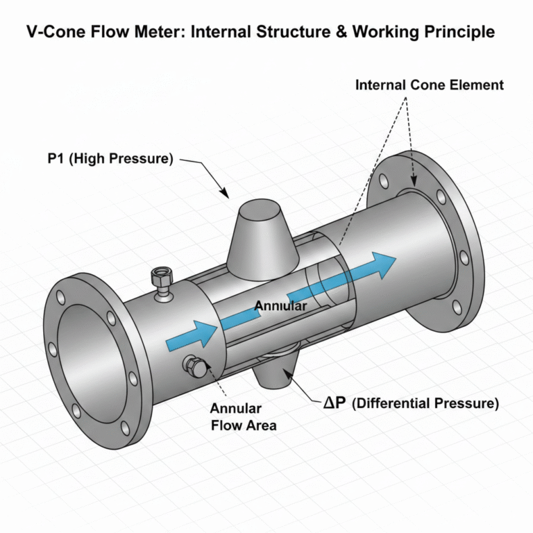
When a fully filled pipeline fluid passes through the cone-shaped obstruction inside the meter, the flow area narrows around the cone. This geometry accelerates the fluid and reduces static pressure, creating a measurable differential pressure between the upstream (high pressure) and the low-pressure zone immediately downstream of the cone.
Since differential pressure is proportional to the square of flow rate, the volumetric or mass flow can be accurately calculated using the measured ΔP.
Key innovation:
The V-cone shifts the throttling region away from the pipe center to a stable annular flow path, reshaping the velocity profile and creating a highly repeatable and self-conditioning flow field, even under distorted or turbulent upstream conditions.
3. Main Features & Advantages
High Accuracy & Stability
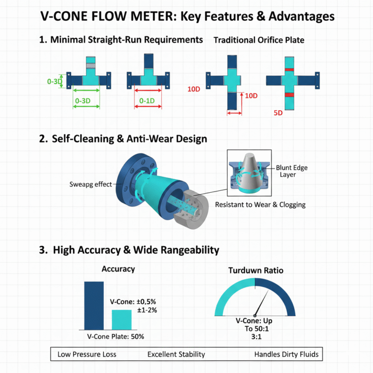
Accuracy up to ±0.5%
Repeatability better than ±0.1%
Blunt-edge cone design forms a boundary layer that protects the cone from wear caused by dirty or abrasive media
Long-term stability without frequent recalibration
Minimal Straight-Run Requirements
Upstream: 0–3D, Downstream: 0–1D
Significantly shorter than traditional orifice plates (10D/5D)
Ideal for space-restricted installations and retrofit projects
Wide Rangeability
Typical turndown ratio: 10:1, up to 50:1
Suitable for low, medium, and high Reynolds numbers
Durability & Low Maintenance
Cone shape generates a “sweeping” effect that prevents buildup
Excellent resistance to erosion and contamination
Self-cleaning flow path ensures stable long-term performance
Low Permanent Pressure Loss
Pressure loss only 1/3–1/5 of an orifice plate
Comparable to Venturi meters
Reduces system energy consumption
Non-Clogging Design
Annular flow path allows solids and impurities to pass freely
Suitable for dirty, viscous, or multiphase media
4. Technical Specifications
| Parameter | Specification |
|---|---|
| Accuracy | ±0.5%, ±1.0% |
| Working Pressure | ≤16 MPa (up to 40 MPa optional) |
| Process Temperature | -40°C to 850°C |
| Ambient Temperature | -40°C to 70°C |
| Pipe Size | DN15–DN3000 |
| Output | 4–20 mA |
| Power Supply | 24 VDC |
| Turndown Ratio | 10:1 (max. 50:1) |
| Repeatability | <0.1% |
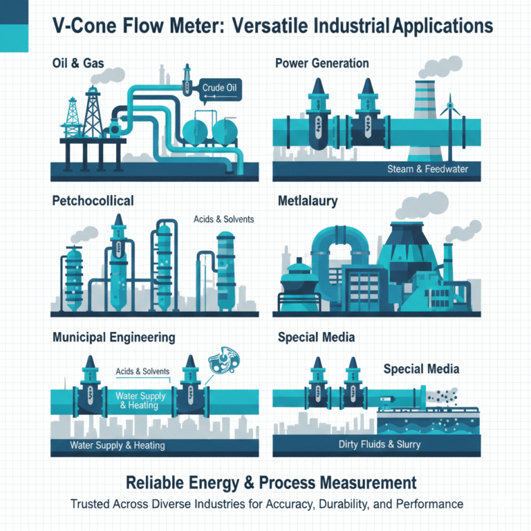
5. Application Areas
5.1 Industrial Sectors
Oil & Gas: crude oil, fuel oil, residue oil
Petrochemical & Chemical: acids, solvents, process fluids
Power Generation: steam, feedwater, condensate
Metallurgy: blast furnace gas, coke oven gas, oxygen
Municipal Engineering: water supply, district heating systems
5.2 Media Types
Gases: natural gas, air, flue gas
Liquids: water, hydrocarbons, chemicals
Steam: saturated and superheated
Special media: dirty fluids, slurry, gas–liquid two-phase flow
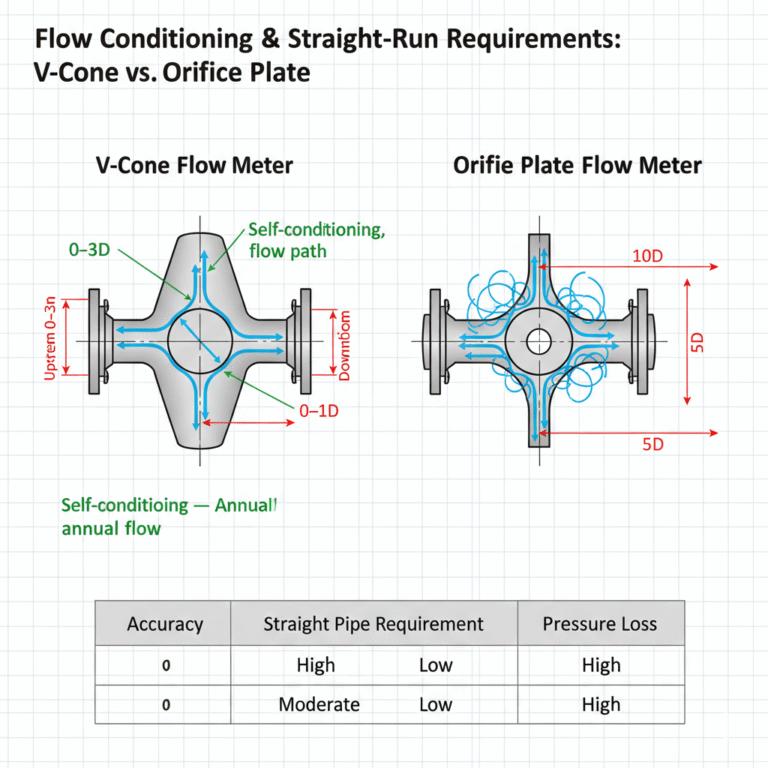
6. Comparison with Traditional Orifice Plates
| Performance Indicator | V-Cone Flow Meter | Orifice Plate |
|---|---|---|
| Accuracy | ±0.5% | ±1–2% |
| Straight Pipe Requirement | 0–3D upstream / 0–1D downstream | 10D / 5D |
| Turndown Ratio | Up to 15:1 | 3:1 |
| Pressure Loss | Low | High |
| Long-Term Stability | Excellent | Moderate |
| Suitable Media | Clean & dirty media | Mostly clean |
7. Installation Guidelines
7.1 Installation Environment
Avoid strong vibration areas
Reduce exposure to extreme temperatures or direct sunlight
Ensure good ventilation in corrosive environments
7.2 Installation Methods
Flanged type: DN50–DN3000; ideal for high-temperature or steam service
Wafer type: for small diameters; similar to vortex flow meter installation
Small-diameter integrated type: ≤DN40, fluid temperature ≤120°C
Butt-weld type: economical option for larger pipelines
7.3 Special Media Precautions
Steam: condensate pots must not be installed at the lowest point to avoid measurement error
Liquids in cold climates: protect transmitter chamber from freezing
8. Selection Guide
To size and select a V-cone flow meter, the following data is required:
Fluid name
Pipe inner/outer diameter
Flow units (kg/h, t/h, m³/h, Nm³/h)
Minimum, maximum, and normal flow rates
Operating pressure (MPa)
Temperature (°C)
Fluid density (kg/m³)
Preferred installation direction (horizontal/vertical)
Note:
Although highly versatile, V-cone meters must be selected based on actual process conditions to ensure measurement reliability.
9. Maintenance Recommendations
The V-cone has low maintenance requirements but periodic checks are recommended:
Inspect cone and pipe interior for buildup
Clean if necessary
Check all seals for leakage
Calibrate the differential pressure transmitter at intervals
Extra inspection for devices operating under extreme high-pressure or high-temperature conditions
10. Conclusion
The V-cone flow meter is a robust, accurate, and low-maintenance differential-pressure device that offers a superior alternative to traditional orifice plates. With excellent long-term stability, wide rangeability, low installation requirements, and compatibility with challenging media, it is increasingly adopted across oil & gas, chemicals, power, metallurgy, and municipal applications for reliable energy and process measurement.