1. Purpose & Scope
This document provides a structured, methodical approach to diagnosing faults in industrial instruments and control loops. It is intended for maintenance engineers, instrument technicians, and commissioning teams working on transmitters, indicators, recorders, PLC/RTU I/O, and ancillary devices.
2. Safety & ESD Precautions
De-energize circuits whenever practical; apply lock-out/tag-out (LOTO).
Verify absence of hazardous voltages before touching conductors.
Use insulated tools and PPE appropriate to arc-flash category.
Observe ESD handling for sensitive electronics (use wrist strap, ESD mat).
Discharge large capacitors before handling power supplies or drives.
3. Recommended Test Equipment
True-RMS digital multimeter (CAT III/IV rated)
Loop calibrator / 24 VDC loop supply with measure/simulate 4–20 mA
Handheld oscilloscope (or scope meter) for ripple, noise, and signals
Insulation resistance tester (as required; never on live/connected electronics)
Signal injector/simulator (mA, V, RTD/TC, frequency/pulse)
Portable HART/fieldbus communicator (if applicable)
Non-contact IR thermometer; contact thermocouple probe for hot spots
Clamp meter (mA DC capable) and continuity beeper
Spare fuses, terminal jumpers, 120 Ω/250 Ω resistors for quick tests
4. Quick Diagnostic Workflow (5 Steps)
Stabilize & Document — Record symptom, timestamps, alarms, environmental conditions.
Visual & Power Checks — Look for damage, wiring errors, blown fuses; verify supply.
Localize the Loop — Field device ↔ wiring ↔ junction box ↔ panel I/O ↔ controller/HMI.
Choose Methods — Apply one or more of the 10 methods below to isolate root cause.
Fix, Verify, Prevent — Correct fault, function-test, update drawings, log the action.
5. Fault Symptom → Likely Cause (Quick Map)
| Symptom | Likely Causes | First Checks |
|---|---|---|
| No display / dead instrument | No power, blown fuse, reversed polarity, internal PSU failure | Supply voltage at terminals; fuses; polarity |
| Output stuck at 3.6–4 mA | Sensor open, mis-range, LRV underrange, AI scaling error | Sensor continuity; range; AI raw counts |
| Output pegged at 20–21 mA | Sensor short, over-range, loop resistance too high, EMI | Loop resistance; sensor reading; shielding/ground |
| Random spikes / noise | Ground loops, poor shielding, VFD/EMI coupling, loose terminals | Shield continuity/termination; re-torque terminals |
| Intermittent dropouts | Loose connectors, moisture ingress, vibration, temperature drift | Wiggle test; inspect glands; temperature hotspots |
| Communication failure | Wrong address/baud, terminations, polarity swap, missing bias | RS-485 A/B swap; 120 Ω term; bias resistors |
6. Ten Core Troubleshooting Methods (Expanded)
1) Visual Inspection
Goal: Find obvious mechanical/electrical issues without tools.
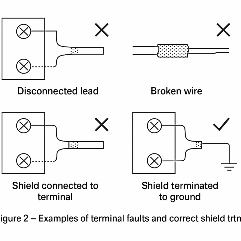
Checklist: cracked housings, loose glands, missing seals, corrosion, burnt components, bulged capacitors, discolored PCB, mis-set DIP/rotary switches, incorrect range links, poor crimping, stray wire whiskers, wrong terminal numbers, improper shield termination (both ends vs single-point).
2) Interview & History (“Investigation”)
Goal: Reconstruct the fault timeline and operating context.
Ask: What changed (process, firmware, wiring, nearby equipment)? When? Any lightning/storms, washdowns, maintenance, welding, or VFD commissioning? Capture alarm codes, error logs, and previous repairs. Distinguish after-repair faults from in-service faults.
3) Isolation / Open-Loop (“Break” Method)
Goal: Decide which block causes the symptom by temporarily opening the loop.
Procedure:
Open series jumpers to separate field device ↔ cable ↔ panel I/O.
Observe if fault disappears when a section is disconnected.
For current loops, break the loop and insert a loop calibrator as a known source/sink to test each segment independently.
Notes: Avoid using this on tightly coupled high-gain control loops without bypass/manual mode.
4) Shorting / Bridging (“Short” Method)
Goal: Prove whether the fault is before or after a given stage by temporary short.
Examples:
Briefly short a differential input to confirm noise originates upstream.
Bridge an RTD input across a known reference to check AI linearity.
Short a transistor output to common via a test resistor to validate DO path.
Caution: Only apply where safe and designed for (e.g., low-level inputs). Never short mains or power rails.

5) Substitution (“Swap” Method)
Goal: Prove a suspect component by replacing it with a known-good unit.
Best Practices:
Substitute like-for-like ranges and firmware where possible.
If the replacement fails again, investigate upstream causes (over-voltage, mis-wiring, condensation) to avoid repeat damage.
6) Sectionalization (“Divide & Conquer”)
Goal: Break the system into functional sections and test from big to small.
Typical Sections: External loop (sensors/actuators), power supplies, internal electronics/I/O, communications, and control logic.
Tip: Start at the interfaces (power and I/O) before deep PCB analysis.
7) Touch/Noise Injection Test (Human-Body Interference)
Goal: Use weak capacitive coupling from a finger or test lead to see stage reaction.
Use Cases: Audio/low-frequency signal paths, high-impedance sensor inputs.
Caution: Observe safety. Do not touch high-voltage or exposed PSU sections. Prefer a long insulated lead as a “probe” to inject ambient hum.
8) Voltage Method
Goal: Compare measured DC/AC voltages with expected values.
Guidelines:
24 VDC control rails: expect 24 V ±10% under load; check ripple (<200 mVpp typical).
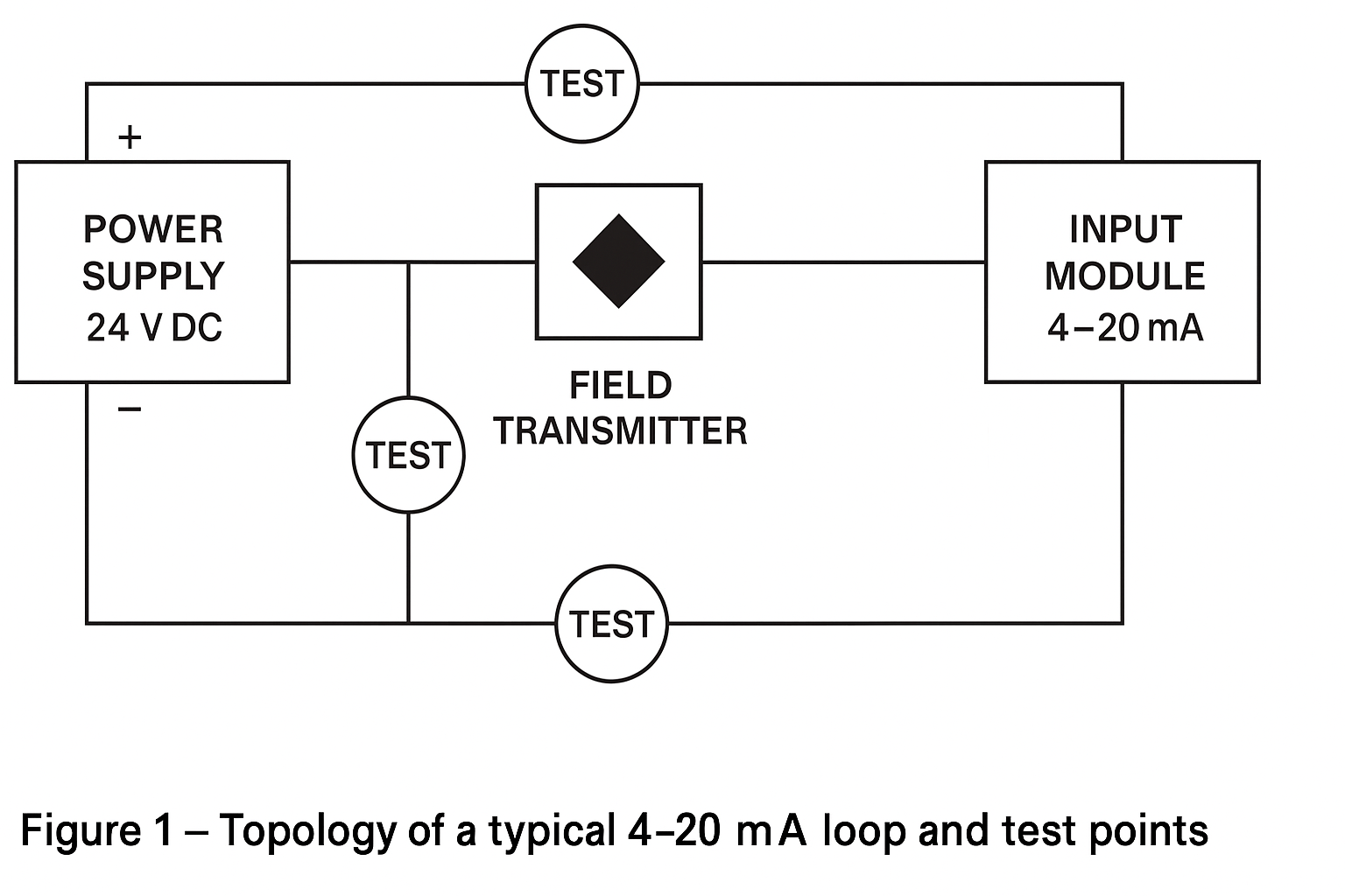
4–20 mA across 250 Ω: 1–5 V.
Discrete PNP sensors: 24 V logic high; check under load.
AC mains into PSU: confirm correct taps and frequency.
Tip: Map “normal” voltages at key test points for future reference.
9) Current Method
Goal: Detect abnormal consumption or loop current.
Direct: Break the loop and insert an ammeter or loop calibrator.
Indirect: Measure voltage drop across known shunt (e.g., 250 Ω) and compute I = V/R.
Examples:
AI reading low? Measure actual loop current vs AI raw counts.
PSU overload? Clamp output leads to see if a branch is drawing excess.
10) Resistance & Continuity Method
Goal: Find opens, shorts, or high-resistance joints with power removed.
Steps:
Continuity on sensor leads, JB terminals, and marshalling panels.
Measure loop resistance end-to-end and compare to cable spec + device burden.
Insulation tests for field wiring when disconnected from electronics.
Caution: Never use insulation tester on connected electronics.

7. Worked Examples
A) 4–20 mA Level Transmitter Reads 2 mA (Underrange)
Visual: check condensation in head, desiccant, cable gland.
Voltage: 24 V at transmitter? ≥12 V at device under full load?
Current: loop at AI card via 250 Ω = ~0.5 V → 2 mA; simulate 12 mA with calibrator at panel—if AI tracks, field device/wiring is suspect.
Isolation: connect calibrator at field end—if panel reads correct, cabling OK → transmitter fault or sensor issue.
Substitution: swap transmitter or sensor element to confirm.
B) RS-485 Temperature Network “No Response”
Visual: A/B swapped? Loose shield/drain wire? Termination present at both ends only?
Investigation: baud/parity/address changed recently?
Voltage: idle bias (A-B ≈ +200 mV to +500 mV) present?
Sectionalization: test single node directly at gateway with short stub.
Substitution: known-good converter and short patch cable.
C) Random Spikes on Pressure Trend Near VFD
Investigation: new drive commissioned yesterday.
Visual: shield grounded at single point? Analog and power segregated?
Voltage (scope): observe ripple/noise on 24 V rail and AI.
Mitigation test (short/bridge): add temporary 250 Ω/1 µF RC at AI, reroute cable, or enable VFD output filter; if spikes reduce, implement permanent solution (Ferrites, proper cable, separation, single-point shield).

8. Commissioning & Maintenance Checklists
Power & Ground
24 VDC rails within ±10% under load; ripple acceptable
Protective earth continuity; no ground loops between cabinets
Correct fuses/breakers fitted; spares available
Wiring & Terminations
Torque-checked terminals; no loose strands
Shields terminated at designated end only
Glands sealed; drain loops formed; no water paths
I/O & Loops
Analog inputs calibrated at 0%, 50%, 100% points
Analog outputs drive/track load across range
Discrete I/O logic verified (active state, debounce)
Communication nodes: address/baud/parity/termination validated
Documentation
As-built drawings updated
Ranges/scaling noted in controller and HMI
Fault log completed with root cause and corrective action
9. Preventive Actions (Reduce Recurrence)
Use conformal-coated electronics in humid/corrosive areas; maintain desiccants.
Specify proper cable type (twisted pair, shielded, low-capacitance) and segregate from power/VFD routes.
Implement surge protection on outdoor lines; bond shields correctly.
Standardize 250 Ω sense resistors and provide test jacks across them.
Maintain spares of critical instruments with pre-loaded configurations.
Periodically thermal-scan panels to catch loose/high-resistance joints.

10. Templates
A) Fault Report (Example Fields)
Asset tag / loop ID / location
Symptom & time observed
Process conditions (P/T/flow, mode)
Methods applied (IDs 1–10) & measurements
Root cause & corrective action
Verification step & sign-off
Preventive recommendation
B) Loop Reference Table (Fill-In)
| Loop ID | Sensor Type | Range | Power | Expected Values | Notes |
|---|---|---|---|---|---|
| LT-101 | 4–20 mA | 0–5 m | 24 VDC | 0%≈4 mA; 50%≈12 mA; 100%≈20 mA | 250 Ω at AI = 1–5 V |