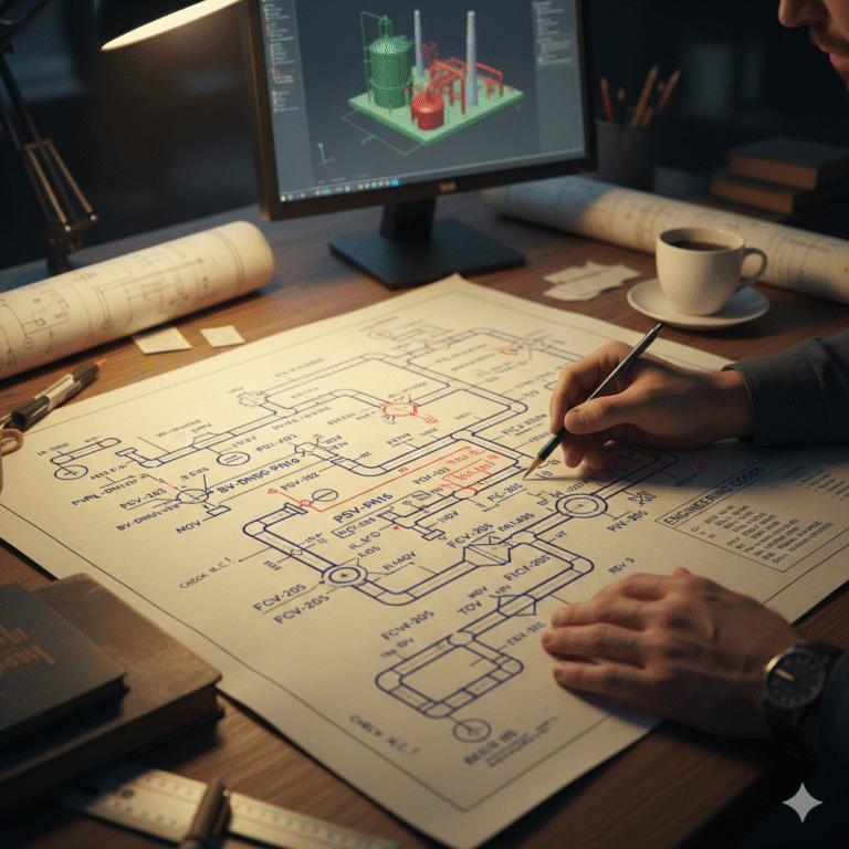
When engineers first look at a piping or P&ID drawing, one thing becomes immediately noticeable: there are not many words, but there are many letter combinations.
These letters are what we commonly call valve and piping codes. At first glance, they may look complicated, but in reality, they are simply a compact way of expressing technical information.
1. What Do Valve and Piping Codes Represent?
If we compare an engineering drawing to a map, then valve and piping codes act like road signs.
Instead of writing full equipment names, codes are used to quickly indicate:
what type of equipment it is
what function it performs in the system
its general size or pressure class
Once this concept is understood, reading these codes becomes much more intuitive and far less intimidating.
2. Common Valve Codes
Valves appear frequently in process systems, especially isolation valves, which usually represent the largest quantity in a piping network.
Isolation and Shut-Off Valves
These valves are mainly used to isolate pipelines or equipment:
GV – Gate Valve
DV – Globe Valve
BV – Ball Valve (in some projects, BV may also be used for butterfly valves; always follow project specifications)
SV – Plug Valve
When these codes appear on drawings, they typically indicate isolation points within the system.
Control and Regulating Valves
When the code includes CV, the function changes significantly:
CV – Control Valve
PCV – Pressure Control Valve
TCV – Temperature Control Valve
FCV – Flow Control Valve
LCV – Level Control Valve
These valves are normally installed at critical operating positions. They act as the “regulating center” of the process and are essential for maintaining stable operating conditions.
Safety and Protection Valves
When safety-related codes appear, special attention is required:
PSV – Pressure Safety Valve
PRV – Pressure Reducing / Regulating Valve
RV – Relief Valve
BDV – Blowdown Valve
These valves are directly related to system protection and design limits. Their locations and set parameters are critical for overall plant safety.
Check and Direction Control Valves
These valves prevent reverse flow and are commonly installed downstream of pumps or compressors:
NRV – Non-Return Valve (Check Valve)
DCV – Dual Plate Check Valve
Actuation-Related Codes
These codes describe how a valve is operated:
MOV – Motor Operated Valve
AOV – Air Operated Valve
SOV – Solenoid Operated Valve
SDV – Shutdown Valve
They are often used in combination with main valve codes and are closely related to automation and control systems.
3. Piping Codes
Compared with valves, piping codes focus more on describing the function of the pipeline itself.
Medium-Based Piping Identification
Common examples include:
PW – Process Water
CW – Cooling Water
FW – Feed Water
DW – Drain Water
SW – Sewage Water
IA – Instrument Air
PA – Plant / Process Air
These codes allow engineers to quickly identify the service of a pipeline.
System Function Classification
PL – Process Line
HL – Hot Utility Line
CL – Cooling Line
FL – Fuel Line
VL – Vent Line
When viewed together, these identifiers provide a clear understanding of the pipeline’s role within the process system.
Common Pipe Size and Rating Designations
DN – Nominal Diameter
PN – Nominal Pressure
SCH – Pipe Schedule (wall thickness)
STD / XS / XXS – Standard / Extra Strong / Double Extra Strong
Typical structure example:
Pipeline Code + DN + PN + Material (exact sequence depends on project specifications)
Additional Identification Marks
N.O. – Normally Open
N.C. – Normally Closed
MAN – Manual
AUTO – Automatic
INS – Insulated
HT – Heat Traced
4. The Importance of Numbers in Tag Codes
Letters define the function, while numbers define the capacity.
For example:
BV–DN50–PN16 Means:
Ball Valve
Nominal Diameter 50
Nominal Pressure 16
Another example:
PW–PL–DN100 Indicates:
Process Water
Process Line
Nominal Diameter 100
Even without additional documentation, these codes already provide essential installation and selection information
5. Always Read the Codes as a Complete Set
Valve tags and piping codes should never be interpreted separately.
For example:
PW–PL–DN100 + BV
This indicates:
Process water service
Process pipeline
DN100 size
Equipped with a ball valve
From this information alone, engineers can already visualize the physical configuration of the pipeline.
6. Understanding, Not Memorizing
Valve and piping codes are rarely meant to be memorized mechanically.
With sufficient exposure to drawings, engineers naturally begin to associate codes with real system scenarios. At that point, letters are no longer abstract symbols — they become a concise technical language describing actual process conditions.
In real engineering projects, final interpretation should always follow the project specifications and the P&ID legend provided by the design institute.