Thermocouples are widely used in various industries for temperature measurement due to their simplicity, reliability, and wide temperature range. However, their practical use often raises technical questions. This article addresses some of the most frequently encountered issues and provides solutions to help ensure accurate and stable temperature measurements.

1. Why is the thermocouple output unstable?
Unstable thermocouple readings can arise from multiple factors:
- Broken or nearly broken thermoelectric wires: If the thermoelectric wires are damaged or partially severed, the output may fluctuate.
- Poor contact at connection points: Loose connections between the terminal blocks and thermoelectric wires can lead to unstable readings.
- Short-circuits or grounding issues: Measurement circuit issues, such as intermittent short-circuiting or improper grounding, are common causes.
- External interference: Electromagnetic interference (EMI) from nearby equipment can disrupt signal stability.
Solution: Inspect the thermocouple and its connections regularly. Use shielding cables to minimize electromagnetic interference. If the issue persists, consider using a signal conditioner or isolator.

2. Why is cold-junction compensation required in thermocouple measurements?
Thermocouples generate a voltage (thermoelectric potential) proportional to the temperature difference between the hot junction (measurement point) and the cold junction (reference point). However, this relationship assumes the cold junction temperature is constant at 0°C.
In real-world applications, the cold junction is often exposed to fluctuating ambient temperatures. Without compensation, these variations introduce measurement errors. Cold-junction compensation adjusts for these variations, ensuring accurate temperature readings.
Example: If the hot junction measures 200°C and the cold junction temperature fluctuates between 20°C and 25°C without compensation, your readings could vary by up to 5°C, a significant error for precision applications.

3. Why should the reference junction temperature be fixed at 0°C?
The standard thermocouple calibration tables assume a reference junction temperature of 0°C. Fixing the reference at this value simplifies calculations and ensures compatibility with standardized instrumentation.
Practical Note: If fixing the reference at 0°C is impractical, corrections must be applied using compensation techniques. This ensures the measured temperature corresponds to the calibration standards.
4. What are the three key thermocouple measurement laws?
- Homogeneous Circuit Law: A closed circuit made of a single material, regardless of temperature gradients or variations in cross-section, cannot generate a thermoelectric potential.
- Intermediate Temperature Law: In circuits made of dissimilar materials, if all junctions are at the same temperature, the net thermoelectric potential is zero.
- Superposition Law: The thermoelectric potential between two junctions at temperatures T1 and T3 equals the algebraic sum of the potentials from junctions at T1 to T2 and T2 to T3.

5. How can cold-junction compensation be implemented?
Methods for Compensation:
Constant-Temperature Method:
- Use a thermostatic device (such as an ice-point reference or zero-point bath) to maintain the cold junction at a stable temperature, typically 0°C.
Compensation Method:
- Fixed Temperature Compensation: If the cold junction temperature remains constant at a non-zero value, apply a mathematical correction: E(T,T0)=E(T,Tn)+E(Tn,T0) where T is 0°C, Tn is the fixed temperature, and E represents the thermoelectric potential.
- Variable Temperature Compensation: For fluctuating cold junction temperatures, use:
- Compensation Cables: Extend the thermocouple’s lead wires to a location with more stable environmental conditions.
- Thermal Devices: Place the junction in a temperature-controlled environment, like a thermostatic chamber.
- Electronic Compensation: Incorporate a compensation circuit or temperature sensor into the measurement system to automatically adjust for ambient temperature changes.
Example in Industry: For high-precision laboratories, the constant-temperature method with ice baths is preferred. In industrial settings, electronic compensation using microcontrollers is more practical.

6. Practical Tips for Reliable Thermocouple Use
- Use proper shielding: Minimize EMI by using shielded cables or running thermocouple wires away from high-power equipment.
- Regular maintenance: Inspect the thermocouple junctions and wiring for damage or loose connections.
- Choose the right thermocouple type: Select a thermocouple with appropriate materials and temperature ranges for your specific application.

Adding Visuals for Better Understanding
- Diagram: Show a thermocouple circuit, labeling the hot junction, cold junction, and compensation elements.
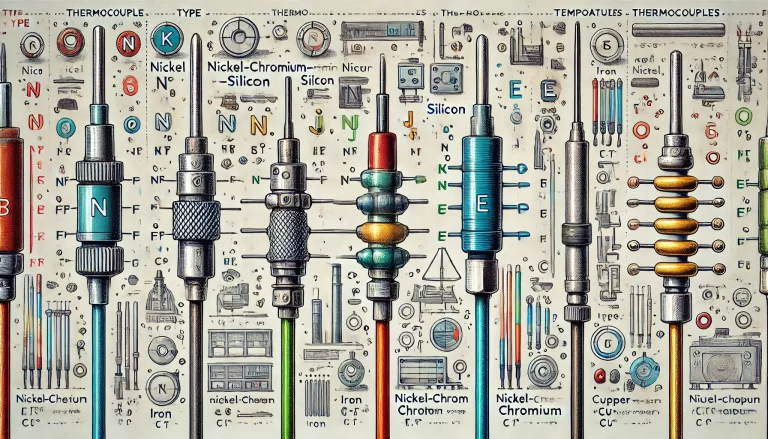
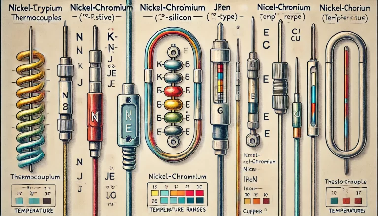
- Table: Include a comparison of common thermocouple types (e.g., Type K, Type J) with their temperature ranges and applications.
- Flowchart: Illustrate the decision-making process for choosing the appropriate cold-junction compensation method.
