In industrial automation and instrumentation, the terms RS-485 and Modbus frequently appear together. However, they refer to two different layers of communication. Understanding the distinction between them is essential when selecting and configuring communication interfaces in industrial devices such as flow meters, temperature transmitters, or programmable logic controllers (PLCs).
2. What is RS-485?
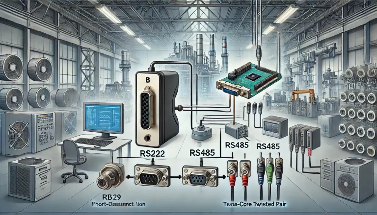
RS-485 (also known as EIA-485) is a physical layer standard that defines the electrical characteristics of drivers and receivers for use in serial communications systems.
Key Features of RS-485:
Differential signaling: Increases noise immunity over long distances.
Multi-point capability: Supports up to 32 nodes on a single bus (and even more with repeaters).
Distance: Up to 1200 meters at lower baud rates (typically 9600–115200 bps).
Wiring: Typically uses twisted-pair cables (e.g., A/B lines, sometimes with a ground wire).
RS-485 does not define how data is structured or interpreted—it only defines how data is physically transmitted and received.
3. What is Modbus?
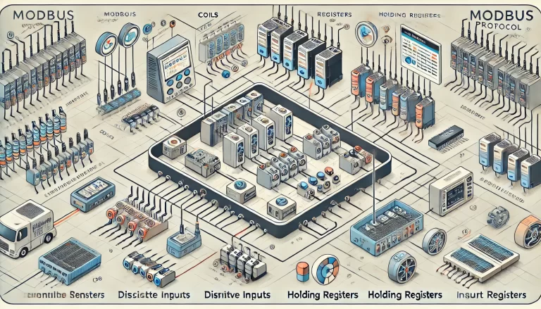
Modbus is a communication protocol developed by Modicon in 1979. It defines the rules for data exchange between devices. Modbus can operate over several physical layers, including RS-232, RS-485, and TCP/IP.
Common Modbus Variants:
Modbus RTU (Remote Terminal Unit): Compact binary representation; commonly used over RS-485.
Modbus ASCII: ASCII-encoded messages; less efficient, more human-readable.
Modbus TCP: Ethernet-based protocol running over TCP/IP.
Addressing scheme (each device has a unique slave ID)
CRC error checking for data integrity
Modbus defines how the data should be packaged, addressed, and interpreted—not how it is physically transmitted.
4. How RS-485 and Modbus Work Together
In most industrial applications, Modbus RTU is implemented over RS-485. This combination takes advantage of RS-485’s robust hardware layer and Modbus RTU’s simple and effective protocol.
Example Setup:
Physical Layer: RS-485 twisted-pair cable
Protocol Layer: Modbus RTU
Topology: One Modbus Master (e.g., PLC) and multiple Modbus Slaves (e.g., flowmeters, transmitters)
This structure enables efficient, long-distance, and multi-device communication using standardized commands.
5. Key Differences and Summary Table
Category
RS-485
Modbus RTU
Layer
Physical Layer
Protocol Layer
Function
Electrical signal transmission
Defines data format and rules
Standard Type
Hardware standard (EIA)
Communication protocol (software)
Topology
Multi-drop, 32+ devices
Master-slave over serial lines
Common Use Together
Yes, widely combined in industry
Often runs on RS-485
6. Practical Tips for System Integrators
Always confirm both physical interface and protocol support in device manuals. A device labeled “RS-485” doesn’t necessarily use Modbus.
Ensure that all devices on the RS-485 network share the same baud rate, parity, stop bits, and Modbus ID range.
Properly terminate the RS-485 bus with 120-ohm resistors at both ends to reduce signal reflection.
7. Conclusion
RS-485 and Modbus are often used together but refer to different aspects of industrial communication. RS-485 handles how data travels, while Modbus defines what the data means. Understanding this layered relationship is crucial for designing and maintaining reliable automation networks.