Magnetic float level transmitters are widely used for liquid level measurement in tanks, reactors, boilers, and other industrial applications. These devices combine visual level indication with remote signal output, offering high reliability and stability even in complex environments such as high temperature, high pressure, or corrosive conditions. This article will guide you through the installation, commissioning, and maintenance of magnetic float level transmitters.
Pre-Installation Preparation
Before starting the installation, ensure that all necessary preparations are made:
Device Check: Confirm that the level transmitter’s measuring tube and float chamber are undamaged, and that the float moves freely. Check that the remote modules (such as transmitters and junction boxes) are properly connected and undamaged.
Parameter Verification: Select appropriate materials based on the medium’s temperature, pressure, and corrosiveness (e.g., 304 stainless steel, PVC, or titanium alloy). Ensure the flange specifications (DN20~DN125) are appropriate.
Tools: Ensure all required tools are on hand, including a wrench, level, measuring tape, sealing gaskets, insulating tape, and a multimeter.
Installation on Site
Choosing the Installation Location
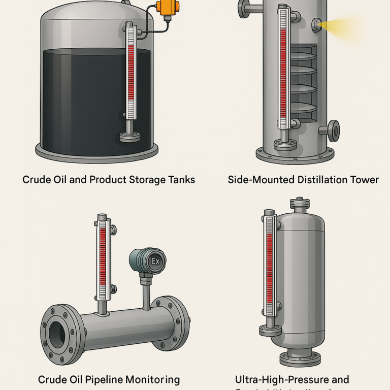
Side-Mounted: Align the zero point of the level transmitter with the lowest liquid level in the container, ensuring the vertical deviation is no more than 1°.
Top-Mounted: Insert from the top and secure the bottom. The insertion depth should cover the maximum range, with the bottom at least 50mm above the container’s bottom.
Important Tip: Avoid installing the transmitter near feed inlets or stirrers to prevent turbulence that could affect the float’s movement.
Flange Connection and Protection
Use the correct sealing gasket (e.g., a metal-wrapped gasket for high-temperature media) and tighten bolts diagonally to avoid skewing. For crystallizing media, install an isolation tank to prevent the float from sticking.
Installing the Remote Transmission Module
Mount the transmitter close to the float chamber to ensure magnetic alignment (distance ≤ 5mm). Make sure the junction box is waterproof and dustproof. For outdoor installations, use a rain shield. Route the signal cables away from power cables to avoid interference.

Piping and Auxiliary Devices
To facilitate maintenance and calibration:
Install a drain valve (DN15~DN20) at the bottom of the level transmitter for cleaning and calibration.
For high-temperature media, install a shut-off valve to isolate the medium during maintenance.
Commissioning Steps
Mechanical Calibration (Local Display)
Zero Calibration: Lower the liquid to the minimum level, ensuring that the float indicates “0”. If there is any deviation, adjust the position of the float chamber.
Float Flexibility: Slowly inject liquid and check if the float moves smoothly and the color remains clear without sticking.
Remote Signal Calibration
Connect the remote transmission module to the control system (DCS/PLC) as per the wiring diagram. Confirm that the 24V power supply and signal wiring are correct, ensuring the shield is grounded at one end in the control room.
Zero Calibration: When the liquid level is at zero, the remote output should be 4 mA. Use the “Z” (zero) knob to adjust.
Span Calibration: Raise the liquid level to full scale, and the output should be 20 mA. Use the “SPAN” knob to adjust and ensure the signal matches the liquid level linearly.
Linear Verification: After zero and span calibration, perform linear verification at 0%, 25%, 50%, 75%, and 100% levels. The error should be ≤ ±0.5%FS.
Communication and Interaction Testing
For HART-enabled devices, use a handheld communicator to check the liquid level, signal strength, and ensure consistency with the local display.
During interactive testing, simulate level changes and verify that the control room display synchronizes and triggers alarms correctly.
Usage and Maintenance Tips
Medium Compatibility: Ensure the float material is compatible with the medium (e.g., PTFE floats for corrosive media, samarium-cobalt magnets for high-temperature applications).
Magnetic Interference: Avoid placing motors, electromagnets, or other strong magnetic devices within 1 meter of the level transmitter.
Space Considerations: Leave at least 300mm of space in front of the float for observation and 200mm for the junction box cover.
Safety Regulations: For high-pressure equipment, release pressure before maintenance. In hazardous environments, use explosion-proof modules (Ex dⅡCT4).
Regular Calibration: Check float flexibility and signal linearity every 6 months. For crystallizing media, perform maintenance every 3 months.
Conclusion
The reliability of magnetic float level transmitters depends not only on the product quality but also on proper installation and precise calibration. By following these guidelines carefully, you can ensure the synchronization, stability, and accuracy of both local and remote monitoring, providing reliable long-term measurement and control of liquid levels in industrial applications.