1. Self-Locking
1.1 Definition
Self-locking refers to a control mechanism where a circuit element (e.g., a button or relay) maintains its state after activation, even when the initial trigger is released.
1.2 Working Principle
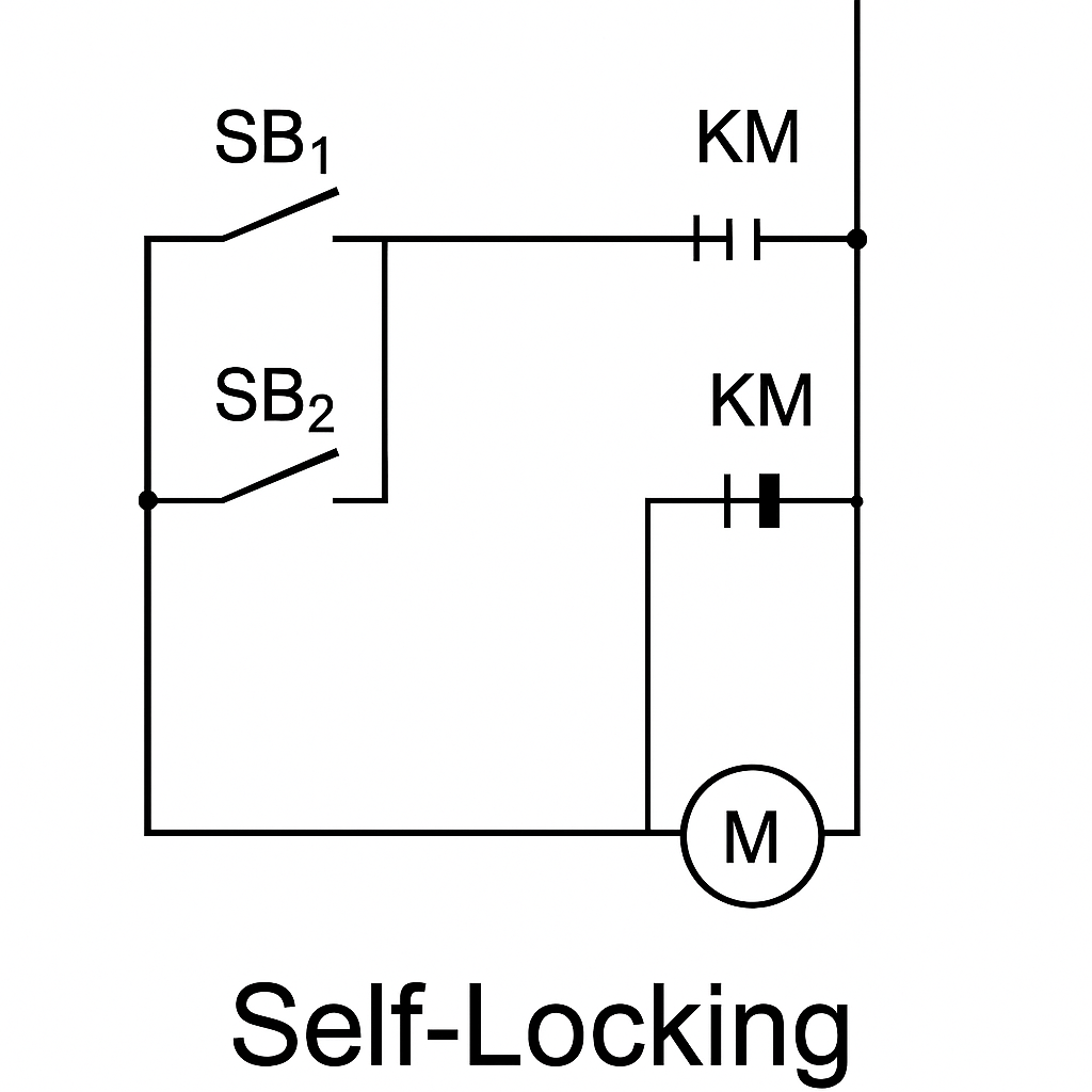
Self-locking is typically achieved by connecting a normally open auxiliary contact of a relay in parallel with the start button. When the button is pressed, the relay is energized, and the auxiliary contact closes to maintain the circuit even after the button is released.
1.3 Application Scenarios
Commonly used in motor start/stop circuits. After pressing the start button, the motor keeps running even if the button is released, until the stop button is pressed.
1.4 Advantages
Simplifies user operation
Eliminates the need for continuous button pressing
1.5 Example
A relay coil is energized through a start button. Its auxiliary contact (NO) closes and maintains the circuit after the button is released.
🔧 Suggested Diagram: Basic motor self-locking control circuit using a relay and push buttons.
2. Interlocking
2.1 Definition
Interlocking is a logic control mechanism where two or more circuits/devices are interdependent, ensuring they do not operate simultaneously or cause a conflict.
2.2 Working Principle
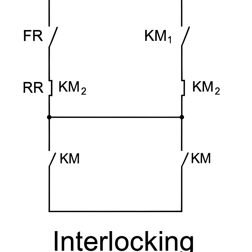
Interlocking is implemented using normally closed (NC) or normally open (NO) contacts to prevent the activation of conflicting devices.
2.3 Application Scenarios
Forward/reverse motor control
Sequential motor startup
Preventing dual operation of exclusive systems
2.4 Advantages
Prevents equipment damage
Ensures safe operation
2.5 Example
In a forward/reverse control circuit, the NC contact of the forward contactor is connected in the coil circuit of the reverse contactor, and vice versa.
🔧 Suggested Diagram: Forward/Reverse interlock circuit using contactor NC contacts.
3. Mutual Locking
3.1 Definition
Mutual locking ensures that two or more devices are interlocked in such a way that their operation is interdependent—they cannot run independently or simultaneously.
3.2 Working Principle
When one device is activated, the mutual locking mechanism ensures the other is either deactivated or prevented from being activated.
3.3 Application Scenarios
Dual power automatic transfer switch (ATS)
Redundant pump control
Safety systems with exclusive modes
3.4 Advantages
Prevents conflicts or dual powering
Enhances operational safety
3.5 Example
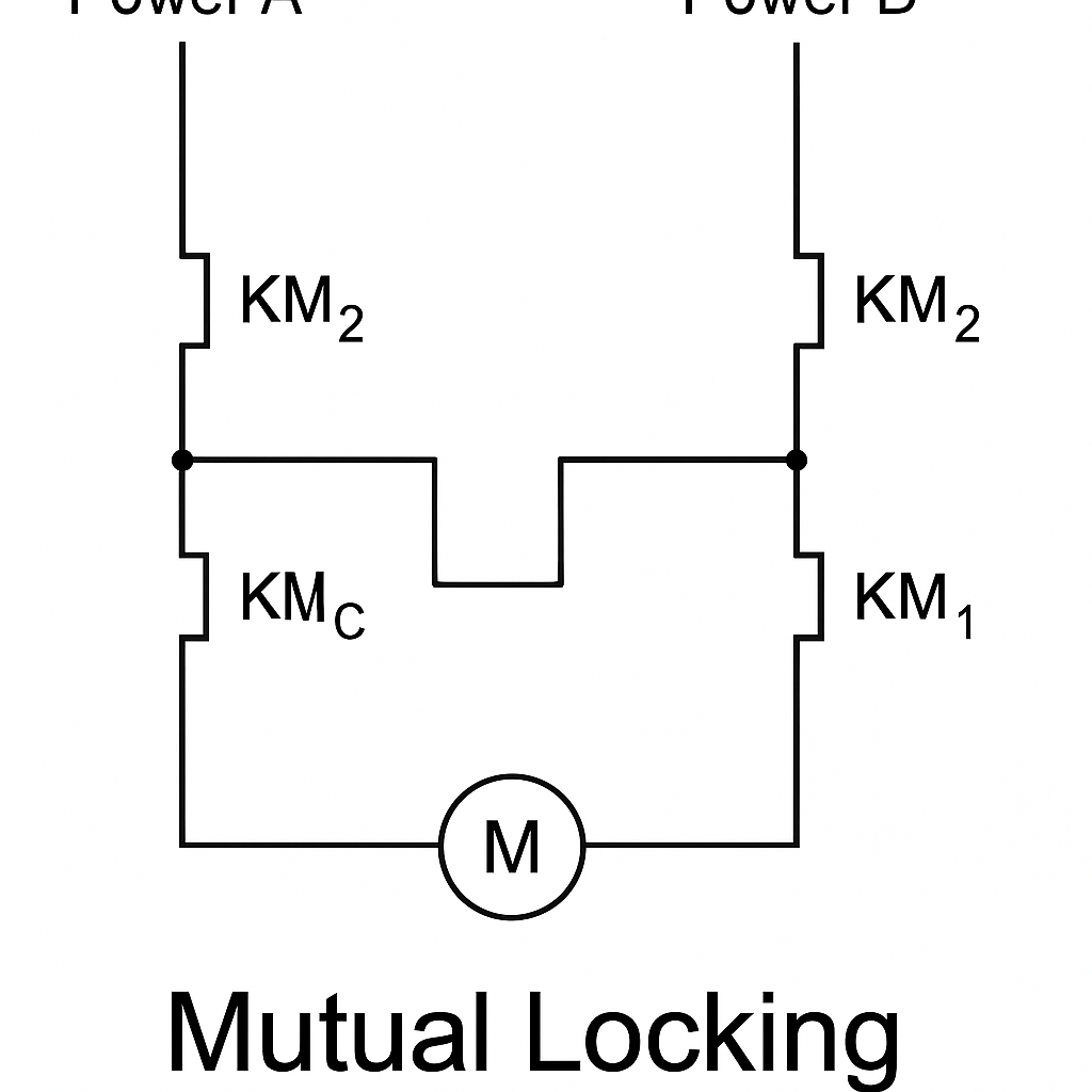
In an ATS, the contactor for Power A has its NC contact in the control loop of Power B, and vice versa. Only one source can be active at a time.
🔧 Suggested Diagram: Mutual interlock between dual power contactors using each other’s NC auxiliary contacts.
4. Comparison Table: Self-Locking vs Interlocking vs Mutual Locking
| Feature | Self-Locking | Interlocking | Mutual Locking |
|---|---|---|---|
| Function | Maintains circuit state | Prevents conflicting operations | Ensures coordinated operation |
| Control Type | Single device’s own contact | Multiple devices in sequence | Multiple devices in opposition |
| Implementation | NO contact in parallel to switch | NC or NO between device circuits | NC contacts cross-wired between |
| Use Cases | Motor start/stop | Forward/reverse motor circuits | Dual power switching |
| Safety Level | Basic convenience | Medium (conflict prevention) | High (mutual exclusivity) |
| Visual Indicator | Simple relay feedback | Coordinated sequence logic | Opposing devices always exclusive |
✅ Summary
Self-locking, interlocking, and mutual locking are foundational logic designs in industrial electrical systems. They ensure safe, reliable, and efficient operation of control equipment:
Self-locking simplifies manual control operations.
Interlocking prevents unsafe simultaneous operations.
Mutual locking ensures exclusive device operation in critical systems.