RS-485 is a widely used communication standard for industrial automation, control systems, and data transmission over long distances. Known for its robustness and noise immunity, RS-485 uses differential signaling to ensure reliable communication even in electrically noisy environments. This article dives into the signal voltage characteristics, input/output requirements, and factors that affect RS-485 performance over long distances.

1. Voltage Levels in RS-485 Communication
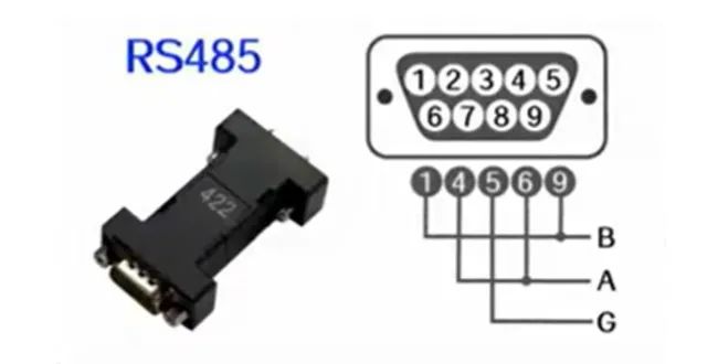
RS-485 transmits data using differential signaling, meaning the data signal is transmitted as the difference between two wires: A and B. This approach ensures that any noise affecting the transmission lines equally will cancel out, improving noise immunity.
- Logic ‘1’ (Mark State):
- The voltage of line A is higher than line B by +1.5V to +5V.
- Example: A = 3V, B = 1V, resulting in a difference of +2V.
- Logic ‘0’ (Space State):
- The voltage of line A is lower than line B by -1.5V to -5V.
- Example: A = 1V, B = 3V, resulting in a difference of -2V.
In RS-485 systems, the absolute voltage levels on each wire can vary, but what matters is the difference between the two lines (A – B).

2. Input Voltage Range of RS-485 Devices
RS-485 devices are designed to operate over a broad range of input voltages to ensure reliability under different conditions.
Input Voltage Range:
- Each line can accept voltages between -7V and +12V. This range helps the system tolerate voltage spikes or common-mode noise that might occur in industrial environments.
Common-Mode Voltage Handling:
- RS-485 devices are designed to handle common-mode voltages (the average voltage of both lines relative to ground) up to ±7V without communication errors.
3. Terminating Resistors and Signal Integrity
To maintain signal integrity over long cables, terminating resistors are used at both ends of the RS-485 bus. These resistors match the characteristic impedance of the transmission line (usually 120 ohms). Proper termination ensures:
- Minimized Signal Reflections: Prevents signal echoes that can distort communication.
- Stable Voltage Levels: Helps maintain consistent differential voltages across the line.
If termination resistors are not used, signals may reflect at the cable ends, causing communication errors, especially at higher data rates.

4. Cable Length and Data Rate Considerations
RS-485 can support long-distance data transmission with minimal signal degradation, but there is a trade-off between cable length and data rate.
- Maximum Distance:
- RS-485 supports distances up to 1200 meters (4000 feet) at lower data rates (e.g., 9600 baud).
- However, as the data rate increases, the maximum cable length decreases. For instance:
- At 100 kbps, the maximum distance is around 400 meters.
- At 1 Mbps, it may drop to 100 meters.
The choice of cable quality (twisted pair, shielded) also plays a significant role in maintaining signal quality over long distances.
5. Noise Immunity and Differential Signaling
One of RS-485’s strengths lies in its differential signaling. Both lines (A and B) transmit complementary signals, so any noise that affects both lines equally will cancel out when the receiver calculates the voltage difference.
- Electromagnetic Interference (EMI) Resistance: RS-485 networks are highly resistant to EMI, making them suitable for harsh industrial environments.
- Ground Loops: Differential signaling reduces the risk of communication issues caused by ground potential differences between devices.

6. RS-485 Multi-Device Communication
Another advantage of RS-485 is its support for multi-point communication. A single RS-485 bus can connect up to 32 devices (transceivers) without repeaters. Advanced RS-485 networks can extend this limit further by using repeaters or lower-impedance drivers.
- Two-Wire Mode: A single twisted pair carries both data and clock signals, making it a half-duplex system.
- Four-Wire Mode: One pair for data transmission and another pair for receiving, enabling full-duplex communication.
7. Applications of RS-485
Due to its robustness, RS-485 is commonly used in the following areas:
- Industrial Automation: Connecting PLCs (Programmable Logic Controllers), sensors, and actuators.
- Building Management Systems (BMS): For HVAC control, lighting systems, and fire alarms.
- Serial Communication Protocols: RS-485 is often used as the physical layer for protocols like Modbus, Profibus, and BACnet.
- Remote Meter Reading: Power meters and water meters frequently use RS-485 for data transmission.

Conclusion
RS-485 is a reliable, noise-resistant communication standard ideal for industrial and commercial applications. Its differential signaling, wide input voltage range, and support for long-distance, multi-device communication make it a preferred choice for environments with significant electrical noise or long transmission paths. By understanding the signal voltage characteristics and best practices for termination and cabling, users can design RS-485 networks that maintain performance and reliability in a variety of conditions.
