Introduction
Process industries, such as oil & gas, chemical manufacturing, and pharmaceuticals, rely on various engineering diagrams to design, analyze, and maintain their operations. Two of the most fundamental diagrams in process engineering are the Process Flow Diagram (PFD) and the Piping and Instrumentation Diagram (P&ID). While both serve as crucial tools in understanding process systems, they have distinct purposes and levels of detail. This article explores their differences, contents, and applications in engineering.
What is a Process Flow Diagram (PFD)?
A Process Flow Diagram (PFD) is a simplified representation of a process that provides an overview of the main components and flow paths within a system. It focuses on high-level process design rather than intricate operational details.
Key Features of PFD:
Represents major equipment such as reactors, heat exchangers, pumps, and separators.
Displays main process streams including gases, liquids, and solids.
Shows mass and energy balances, indicating flow rates, temperature, and pressure at critical points.
Identifies major control loops, though detailed instrumentation is not included.
Uses standardized symbols (e.g., from ANSI, ISO, or DIN standards) to represent equipment and flows.
Applications of PFD:
Conceptual and preliminary process design.
Communication tool among engineers, project managers, and stakeholders.
Reference for economic analysis and feasibility studies.
Basis for developing more detailed engineering diagrams such as P&IDs.
What is a Piping and Instrumentation Diagram (P&ID)?
A Piping and Instrumentation Diagram (P&ID) is a more detailed representation of the process, focusing on piping, control instrumentation, and safety systems. It is crucial for process control, maintenance, and plant operation.
Key Features of P&ID:
Shows all pipes and fittings, including pipe sizes, materials, and identification tags.
Includes valves, pressure relief systems, and flow regulators.
Displays instrumentation (e.g., pressure, temperature, flow rate sensors) and control loops.
Represents safety mechanisms, including alarms, interlocks, and emergency shut-off systems.
Defines process relationships and control strategies, helping operators and engineers understand how the system functions.
Applications of P&ID:
Engineering, procurement, and construction (EPC) projects.
Detailed process control and automation.
Plant maintenance and troubleshooting.
Safety and hazard analysis (e.g., HAZOP studies).
Operator training and plant startup procedures.

Key Differences Between PFD and P&ID
| Aspect | Process Flow Diagram (PFD) | Piping & Instrumentation Diagram (P&ID) |
|---|---|---|
| Purpose | Provides an overview of the process flow | Shows detailed piping, instrumentation, and control systems |
| Detail Level | High-level (general process overview) | Very detailed (engineering and operational details) |
| Components Included | Major equipment, main process lines, process conditions | All equipment, pipes, valves, instruments, and safety devices |
| Instrumentation | Minimal (only key control loops) | Detailed instrumentation, sensors, controllers, alarms |
| Used By | Process engineers, project managers, stakeholders | Control engineers, maintenance teams, safety analysts |
| Applications | Early-stage design, feasibility analysis | Construction, operation, maintenance, troubleshooting |
Example of PFD vs. P&ID
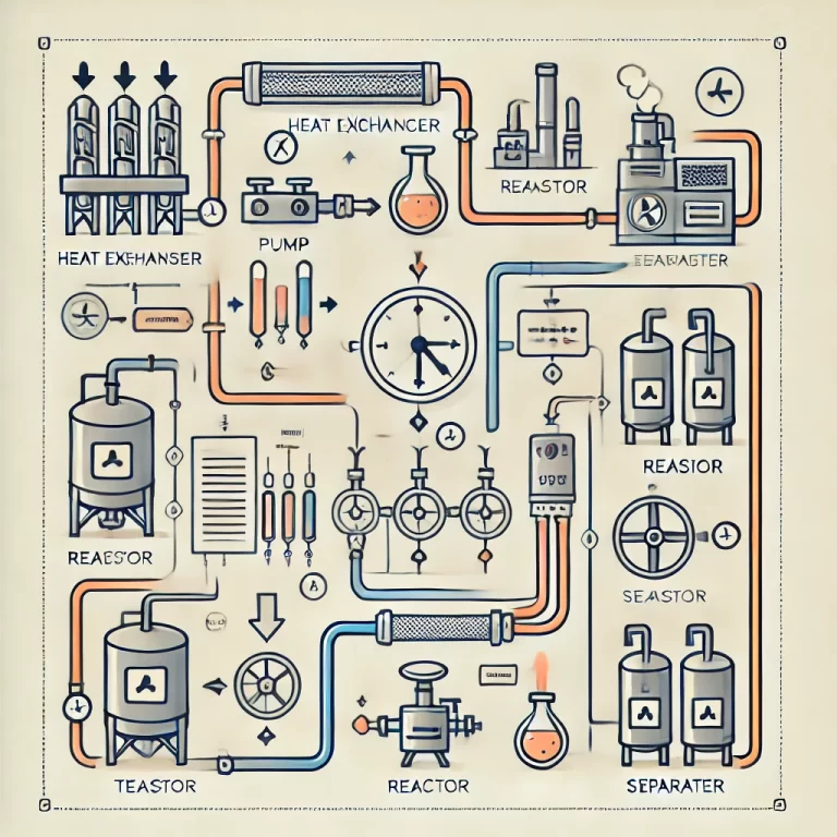
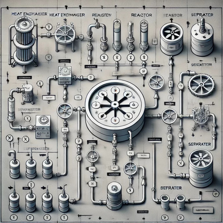
To illustrate the difference, consider a simple heat exchanger system:
PFD Representation: It would show the heat exchanger as a single unit with flow arrows indicating hot and cold streams. It may include inlet and outlet temperatures and flow rates.
P&ID Representation: It would depict all connections, valves, sensors (e.g., temperature, pressure transmitters), controllers, and safety relief valves associated with the heat exchanger.

Conclusion
Both PFDs and P&IDs are essential in process engineering but serve different purposes. PFDs provide a broad overview of a system, while P&IDs give a detailed view necessary for design, construction, and operation. Understanding the distinction between them is crucial for effective process design, safety management, and operational efficiency.
For engineers and plant operators, mastering these diagrams ensures better communication, improved system understanding, and enhanced safety within industrial facilities. By leveraging PFDs for conceptual design and P&IDs for detailed execution, industries can optimize their processes from initial design to long-term maintenance.