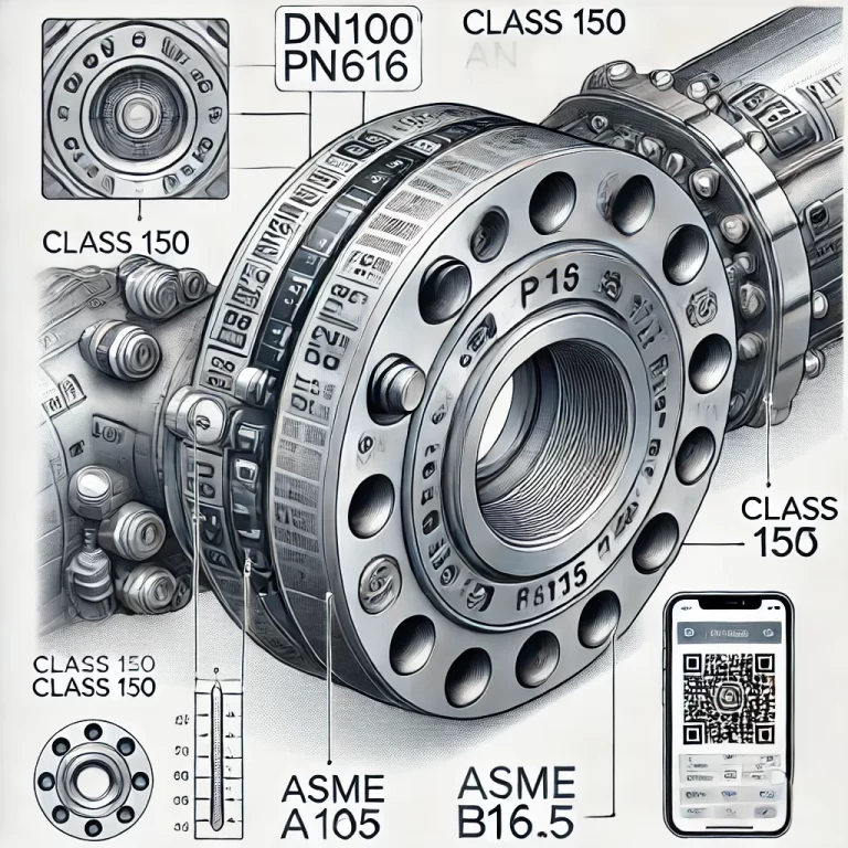
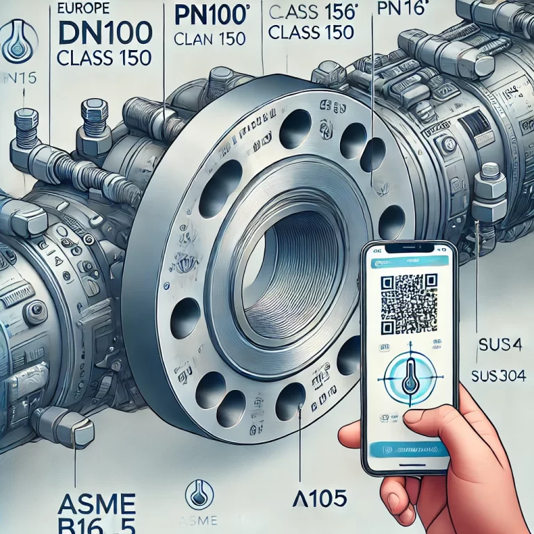
In industrial piping systems, flanges play a vital role in connecting pipelines, valves, pumps, and other equipment. They ensure sealing, mechanical strength, and serviceability. However, many engineers and technicians tend to overlook a crucial aspect: the markings etched onto the flange surface.
These seemingly minor letters and numbers provide essential information that can determine whether a flange is suitable for a specific application. In this article, we’ll break down the meaning of common flange markings and explain why it’s important to pay attention to them.

1. Common Flange Markings and Their Meanings
• DN (Nominal Diameter)
Indicates the nominal pipe size in millimeters. For example, DN100 means the flange is designed for a 100 mm diameter pipe.
• PN (Nominal Pressure)
Represents the pressure rating of the flange. Typical values include PN10, PN16, PN25, etc., measured in bar. In some regions, MPa is used as an alternative unit.
• CLASS (ASME Pressure Rating)
Used in American standards such as ASME B16.5, pressure classes like CLASS 150, CLASS 300 represent different pressure/temperature limits.
• Material Grade
Examples:
A105 – Carbon steel
304/316 – Stainless steel
F22 – Alloy steel Material selection directly affects pressure resistance and corrosion resistance.
• Standard Reference
Indicates the design and manufacturing standard, such as:
ASME B16.5 (American standard)
EN 1092-1 (European standard)
GB/T 9119 (Chinese national standard)
JIS B2220 (Japanese standard)
• Heat Treatment Symbols
Occasionally, flanges are marked with heat treatment conditions, such as:
N – Normalized
QT – Quenched and Tempered These apply to high-pressure or special-use flanges.

2. Why These Markings Matter
✔ Ensure Compatibility
Matching pressure ratings (e.g., PN16 system with PN16 flange) is critical. Using mismatched components can result in underperformance or safety hazards.
✔ Verify Correct Material
Markings help confirm whether the flange is suitable for corrosive, high-temperature, or other demanding environments.
✔ Avoid Dimensional Mismatches
International projects often involve different standards. Mixing ASME and EN flanges can cause bolt-hole misalignment and sealing failures.
✔ Enable Traceability
Markings allow technicians to trace material type, batch number, manufacturer, and specifications—vital for audits and maintenance.
3. Regional Differences in Marking Conventions
| Region | Pressure Marking | Example |
|---|---|---|
| Europe/China | PN | PN10, PN16 |
| USA | CLASS | CLASS 150, 300 |
| Japan | JIS | 10K SUS304 |
4. Real-World Challenges
• Corroded or Faded Markings
After years of service, flange markings may become illegible due to corrosion or mechanical wear. Maintenance teams must then rely on installation records or measurements.
• Misreading or Mislabeling
Mistaking PN25 for PN2.5 can lead to dangerous overpressure situations. Accurate identification is crucial.
• Unmarked or Low-Quality Flanges
Some low-grade flanges lack proper markings, posing a significant safety and compliance risk. Always source components from reputable manufacturers.

5. Smart Markings: The Future of Flange Identification
Modern manufacturers have started implementing QR codes or digital tags on flanges. With a simple scan, you can access:
Material certificates
Test results
Manufacturing records
3D models or CAD files
This trend aligns with the rise of digital plant management and will likely become a standard in the future.
Conclusion
Never underestimate the information carried by flange markings. They represent engineering standards, material safety, and traceability. Before installation, take a moment to verify and record this data—your future self (and maintenance team) will thank you.
