1. What Is an Electrical Schematic Diagram?
An electrical schematic diagram (also known as a wiring diagram or circuit diagram) is a visual representation of an electrical system. It illustrates how various electrical components are connected and how current flows through the system. These diagrams serve as the foundational reference for electrical design, installation, commissioning, maintenance, and fault diagnosis.
2. Key Functions of a Schematic Diagram
Visualizes the working logic of an electrical system
Guides the installation and wiring of control equipment
Assists in troubleshooting and system maintenance
Provides a reference for production and quality inspection
3. Structural Features of a Typical Diagram
Drawn according to control logic, not physical layout
Vertical lines represent control circuits (top to bottom)
Horizontal lines represent power supply circuits (left to right)
The power source is typically placed at the top left or upper section
Control elements (e.g., buttons, relays) are arranged above actuating elements (e.g., motors)
4. Common Electrical Symbols and Meanings
| Component | Symbol (Textual Representation) | Function / Description |
|---|---|---|
| AC/DC Power Supply | ~ / ⎓ | AC or DC voltage source |
| Fuse | ─[ ]─ | Circuit overload protection |
| Switch | ─o/ o─ | Turns circuit ON/OFF |
| Push Button (NO) | ─( )─ | Normally open contact for start operation |
| Contactor Coil | ─( KM )─ | Main control element in motor circuits |
| Contactor Contacts | ─[ ]─ or ─[/]─ | Normally open / closed auxiliary contacts |
| Thermal Overload Relay | ─( FR )─ | Protects motor from overload |
| Motor | ─( M )─ | Final execution device |
| Intermediate Relay | ─( KA )─ | Auxiliary control element |
5. How to Read and Understand a Schematic Diagram
Step-by-Step Approach:
Step 1 – Locate the Power Supply Section
Usually at the top-left of the diagram
Identify voltage and type (e.g., 220V AC, 24V DC)
Step 2 – Identify the Control Circuit
Find push buttons and see how they link to relay coils or contactors
Step 3 – Analyze the Logic
For example:
Pressing the “Start” button energizes the KM coil
KM’s main contact closes → Motor runs
Pressing “Stop” button breaks circuit → KM de-energizes → Motor stops
Step 4 – Trace the Actuating Circuit
Follow the path from power to motor
Ensure contactors or protection devices are correctly placed
Step 5 – Evaluate Protection Components
Look for fuses, thermal relays, and circuit breakers
Check their positions in series with motors or control devices
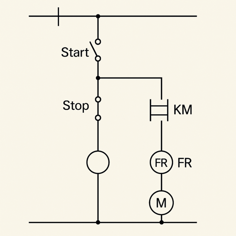
6. Practical Example: Motor Start-Stop Control Circuit
Objective:
Start the motor with a normally open push button and stop it with a normally closed push button. Include a self-holding circuit for automatic retention.
Key Components:
SB1 – Start button (NO)
SB2 – Stop button (NC)
KM – Contactor with auxiliary contact
FR – Thermal overload relay
M – Motor
Operation Logic:
Press SB1 → KM coil is energized
KM’s main contact and auxiliary contact close
Releasing SB1 → KM stays energized via its auxiliary contact (self-holding)
Press SB2 → KM coil de-energizes → Contacts open → Motor stops
7. Schematic Diagram vs. Wiring Diagram
| Category | Schematic Diagram | Wiring Diagram |
|---|---|---|
| Purpose | Logical operation representation | Actual wiring and physical connections |
| Layout | Abstract, logic-based | Real-world layout and positions |
| Audience | Engineers, designers, maintenance staff | Installers, assembly technicians |
| Element Position | Symbolic and functional | Accurate to real-world location |
8. Learning Recommendations
Master standard symbols based on GB/T 4728 or IEC standards
Start with simple circuits such as motor control, relay logic, and star-delta starters
Combine study with actual control cabinet wiring diagrams
Use simulation software like Multisim, EPLAN, or PLC simulators for hands-on practice