In the intricate network of chemical plant automation, discrete, analog, and digital signals form the foundational language between field devices and control systems like PLCs and DCS. Though often confused, these three signal types have distinct roles and characteristics. This article provides a detailed explanation, including definitions, differences, and real-world applications in industrial instrumentation.
1. Signal Types Explained
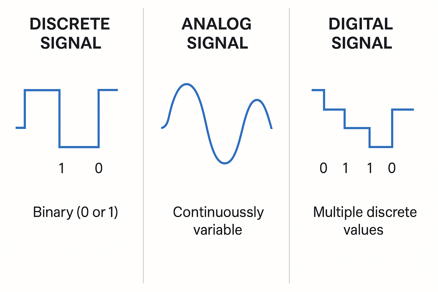
🔌 1.1 Discrete Signal (Binary Contact Signal)
A discrete signal, also known as a binary signal, represents two possible states: ON/OFF, TRUE/FALSE, or 1/0. It is the simplest form of signal and is widely used to indicate device status.
Examples:
A motor temperature controller triggers an auxiliary contact when overheating.
A limit switch on a valve indicates OPEN or CLOSED position.
A contactor or thermal relay outputs ON/OFF status through auxiliary contacts.
Discrete signals can be:
Passive contacts (no internal voltage, powered by the PLC),
Active signals (step voltage or pulse, typically 24VDC), interpreted as logical “1” or “0”.
🔎 Use case: PLCs often use passive discrete inputs to monitor device statuses reliably and simply.
📈 1.2 Analog Signal (Continuously Variable Signal)
An analog signal represents continuously varying physical quantities, such as:
Pressure
Temperature
Flow rate
Voltage (0–10V)
Current (4–20mA)
Unlike discrete signals, analog signals change gradually over time and are used when precise measurement is required.
The PLC analog input module captures these signals and converts them into digital values through sampling and quantization for processing and control.
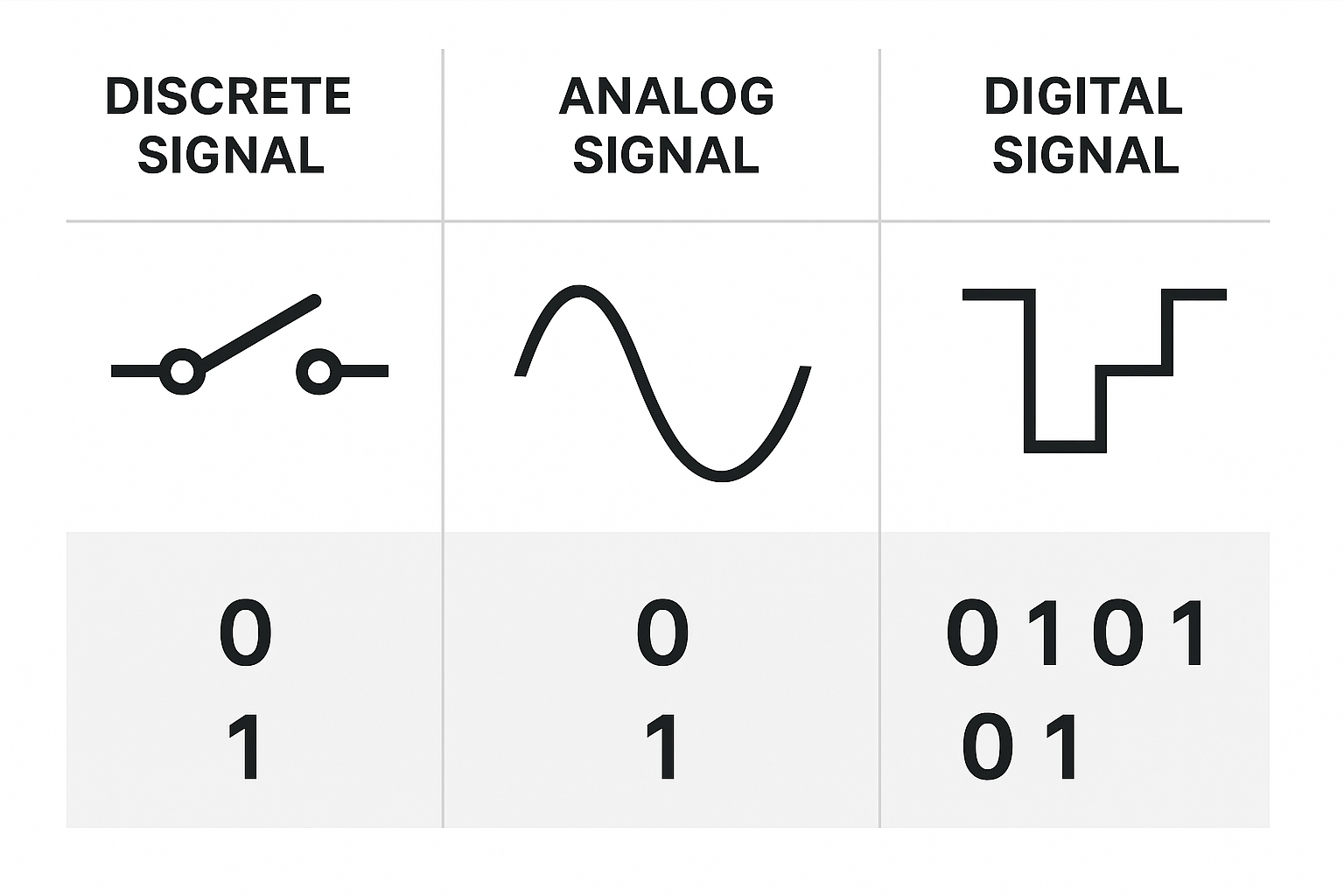
🧠 1.3 Digital Signal (Encoded Binary Data)
A digital signal is formed by a sequence of binary digits (0s and 1s) used to convey more complex information. It can originate from:
Encoded data (e.g., from smart sensors or fieldbus protocols),
Quantized analog signals,
Discrete status inputs.
For instance, a temperature signal exceeding a certain threshold might be digitized into “1” (over-limit), while below the threshold is converted to “0”.
Digital signals are essential in communication and control systems such as Modbus, Profibus, or HART.
2. Comparison Table: Discrete vs Analog vs Digital Signals
| Attribute | Discrete Signal | Analog Signal | Digital Signal |
|---|---|---|---|
| Signal Type | Binary (0/1) | Continuous | Binary-encoded (multiple bits) |
| Application | Status indication | Measurement/control | Data transmission/logic computation |
| Examples | Valve open/close | Flow rate, temperature | Modbus signal, sensor calibration data |
| PLC Interface | DI/DO modules | AI/AO modules | Digital communication modules |
| Susceptibility to Noise | Low | Higher (voltage-based) | Low with proper shielding |
3. Why 4–20 mA Is the Industrial Standard for Analog Signals
Many automation systems standardize analog signals to 4–20 mA current loops instead of 0–10V or 0–20 mA. Here’s why:
🔧 Better Noise Immunity
Voltage signals (like 0–10V) are susceptible to electromagnetic interference (EMI) over long cable runs. Current signals remain stable and immune to voltage drops and EMI, ensuring signal integrity.
🛡 Example: A 0–10V signal may lose accuracy when running over 50 meters of cable in a chemical plant. A 4–20mA current signal remains accurate under the same conditions.
🛠 Easier Fault Diagnosis
With 4–20 mA:
4 mA = zero-level measurement (not a wire break)
0 mA = abnormal (open circuit or device failure)
Using 0–20 mA, a 0 mA reading could either mean zero pressure or a broken wire — hard to distinguish.
4. Conclusion
Understanding the roles and characteristics of discrete, analog, and digital signals is essential for any automation professional. These signals enable real-time monitoring, precise control, and reliable decision-making across industrial processes.
By mastering their differences, engineers can design more robust and responsive instrumentation systems — the backbone of modern chemical plant automation.