Thermocouples are widely used in industrial and scientific applications for temperature measurement. However, for accurate and efficient temperature data transmission, a crucial component known as the compensating wire is used. This article explores the purpose, types, selection criteria, and best practices for using compensating wires in thermocouple systems.
What is a Compensating Wire?
A compensating wire is a specialized wire used to extend the connection between a thermocouple and a measuring instrument, such as a temperature controller or data acquisition system. These wires have similar but not identical thermoelectric characteristics to the thermocouple material within a limited temperature range, helping to minimize measurement errors and cost.
Why is a Compensating Wire Needed?
1. Extending the Thermocouple Connection
Thermocouples are typically installed in high-temperature environments, and it is impractical to use expensive thermocouple materials for long wiring. Compensating wires allow thermocouples to be extended to the measuring instrument economically.
2. Reducing Measurement Errors
If standard copper wires were used to connect a thermocouple to an instrument, additional thermoelectric junctions would be introduced at the connection points, creating extra voltage and leading to inaccurate temperature readings. Compensating wires match the thermocouple characteristics within a specific range to reduce these errors.
3. Cost Reduction
Thermocouples made of materials such as platinum and rhodium can be extremely expensive. Using compensating wires, which are made of more affordable but compatible alloys, significantly reduces the cost of a thermocouple system while maintaining accuracy.
Compensating Wire vs. Extension Wire
Many people confuse compensating wires with extension wires, but they are different:
Feature
Compensating Wire
Extension Wire
Material
Different from thermocouple but similar in properties
Same material as thermocouple
Accuracy
Lower accuracy, but sufficient for moderate environments
Higher accuracy, used in critical applications
Cost
More affordable
Expensive
Usage
Industrial applications where small errors are acceptable
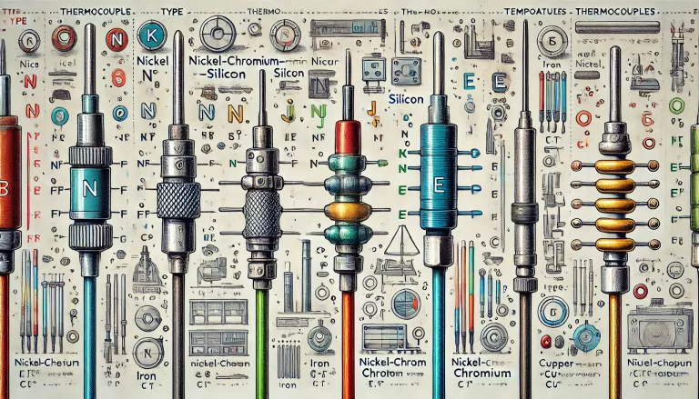
Compensating wires are categorized based on the thermocouple type they support. Each type has different alloy compositions that mimic the thermocouple’s behavior within a limited temperature range.
Common Types:
K-type (Nickel-Chromium/Nickel-Aluminum)
Used for temperatures up to 1,260°C (2,300°F)
Compensating wire code: KC
Common colors: Red (negative) and Green (positive) (per IEC standard)
S-type (Platinum-Rhodium 10%/Platinum)
Used in high-precision temperature control applications
Compensating wire code: SC
Common colors: Red (negative) and Black (positive)
T-type (Copper/Constantan)
Used for low-temperature applications
Compensating wire code: TC
Common colors: Red (negative) and Blue (positive)
Selecting the Right Compensating Wire
Choosing the right compensating wire is crucial for ensuring accuracy in temperature measurement. Consider the following factors:
Thermocouple Type Matching – Always select a compensating wire designed specifically for the thermocouple type in use.
Temperature Range – Ensure that the compensating wire operates within the required ambient temperature range (typically up to 200°C for standard compensating wires).
Environmental Conditions – Use appropriate insulation materials based on the environment (e.g., PVC for general use, fiberglass for high temperatures, and Teflon for chemical resistance).
Length and Resistance – Longer wires introduce resistance, which may affect readings. Choose a wire gauge that minimizes resistance without being impractically thick.
Shielding and Interference Protection – If used in an electrically noisy environment, select shielded compensating wires to minimize signal interference.
Best Practices for Using Compensating Wires
1. Maintain Proper Polarity
Always connect the positive and negative leads correctly. Reversing polarity can introduce incorrect readings.
2. Avoid Long Runs of Compensating Wires
While compensating wires are useful for extending connections, excessive lengths may introduce resistance and potential voltage drops, affecting accuracy.
3. Use Proper Insulation
Select insulation materials suited to the operating environment to prevent degradation and electrical leakage.
4. Keep Away from Electrical Noise
Route compensating wires away from power cables, motors, and other sources of electromagnetic interference to maintain signal integrity.
5. Regularly Calibrate and Inspect Connections
Ensure that all connections are secure and periodically check for wear, corrosion, or other issues that could affect temperature readings.
Conclusion
Compensating wires play a vital role in ensuring accurate and cost-effective temperature measurements in thermocouple systems. By selecting the right compensating wire, following proper installation practices, and maintaining regular inspections, users can achieve reliable and stable temperature readings in various industrial and scientific applications.