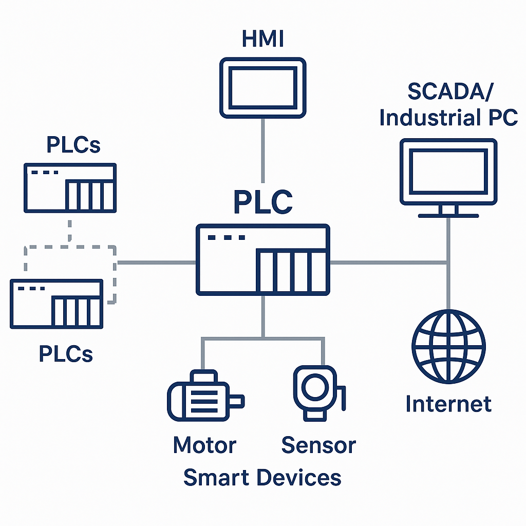
In Programmable Logic Controllers (PLCs), logical operations form the foundation of control strategies. These logic types can be categorized in multiple ways, depending on the data unit used and the nature of the logical behavior. This article introduces the main logic types used in PLC programming and analyzes their characteristics and application implications.
1. Classification by Logical Data Unit
1.1 Bit Logic
Bit logic operates at the bit level. In PLC terms, each bit represents a point—such as an input point, output point, or internal relay point. Bit logic is the fundamental method used in control operations.
Common operations include:
AND
OR
NOT
1.2 Word Logic
Word logic uses multiple bits as a unit, typically a word (16 bits) or even multiple words. Some PLC manufacturers, such as Siemens and Schneider, use the term “channel” instead of “point” and refer to a word as a “channel” or “data word.”
1.3 Flag Value Logic
This type compares a flag value with a preset or expected value. Based on the comparison result, a corresponding logical output is generated.

2. Classification by Logical Nature
2.1 Combinational Logic
In combinational logic, the output depends solely on the current status of inputs, with no regard to historical input states.
Key characteristics:
No feedback loops
Deterministic (single output per input state)
Instantaneous output changes with no intermediate states
Typically simple but requires more input conditions
While such logic circuits are simple, they often don’t require a PLC—examples are used primarily for explanation.
2.2 Sequential (or Temporal) Logic
In sequential logic, outputs depend on both the current input state and the input history. The simplest form of this is the start-hold-stop circuit, where output behavior is influenced by previous button activations.
Key features:
Feedback: Outputs may depend on their own state or latch/set/reset instructions.
Multiple solutions: Same input conditions may lead to different outputs based on history.
Step-wise operation: Circuit behavior unfolds step-by-step or pulse-by-pulse.
Race conditions: Poor design may lead to unstable behavior in asynchronous systems.
PLCs help mitigate many of these issues due to their cyclic and ordered execution, though care must still be taken in the design sequence.

3. Synchronous vs Asynchronous Sequential Logic
3.1 Synchronous Sequential Logic
Driven by a global clock pulse
Reduces timing uncertainty and interaction issues
Easier to design and analyze
3.2 Asynchronous Sequential Logic
No unified clock; relies on signal changes
More complex and prone to timing-related problems (e.g., race conditions)
In practice, the PLC CPU hardware is driven by synchronous logic (clock pulses), but ladder logic execution is sequential, and can behave asynchronously in terms of logical effect.

4. Special Considerations in PLC Sequential Logic
PLCs execute programs cyclically, and logic results are updated only after a full scan cycle.
Differential (edge-detection) instructions can simulate clock pulses:
Positive edge (rising edge): active for one scan when signal changes from 0 to 1.
Negative edge (falling edge): active for one scan when signal changes from 1 to 0.
These can be used to simulate synchrony in otherwise asynchronous logic sections.
5. Summary
Understanding the types of logic—bit vs. word, combinational vs. sequential, synchronous vs. asynchronous—is essential for effective PLC programming and troubleshooting. Each logic type has its own strengths and application scenarios. Properly identifying and applying the right logic structure is key to building robust industrial automation systems.
