For automation engineers, terms like active, passive, powered, and non-powered are commonly encountered. However, many still struggle to clearly differentiate and relate these concepts. This article explains the relationship between transmitter types (active/passive) and DCS I/O card power configurations (powered/non-powered), using a real-world example of the XP351 8-channel AI module.
1. Core Concepts
Active vs Passive Transmitters
Passive Transmitter: Does not have an internal power supply and requires external excitation.
Active Transmitter: Equipped with its own internal power source, capable of supplying output current independently.
Powered vs Non-Powered I/O Cards
Powered Module: Provides a 24V DC supply to external devices (e.g., passive transmitters).
Non-Powered Module: Does not supply voltage to the field; designed to receive signals from active transmitters.
🔄 Mapping Relationship
Powered I/O Module ↔ Passive Transmitter
Non-Powered I/O Module ↔ Active Transmitter
2. Case Study: XP351 AI Module
The XP351 module (by SUPCON) features 8 analog input channels, each configurable via jumper settings:
Jumpers JP1 to JP8 correspond to CH1 to CH8 respectively.
Each jumper controls whether its corresponding channel is powered or non-powered.
Jumper Position
Mode
DCS Module Behavior
Expected Transmitter Type
Pins 1–2
Powered
Provides 24V DC
Passive (no internal power)
Pins 2–3
Non-Powered
No power output
Active (has internal power)
Terminology Note:
Passive Sensor = requires loop power → used with powered module.
Active Sensor = self-powered → used with non-powered module.
3. Wiring Considerations
The polarity of wiring terminals on the I/O module changes based on the power configuration:
For powered channels, the module supplies power, and the transmitter loop connects accordingly.
For non-powered channels, power comes from the transmitter itself, and the module only receives the signal.
Improper jumper settings or incorrect polarity during wiring can result in:
Signal loss
Equipment damage
Erroneous readings
⚠ Always verify jumper settings and terminal polarity before connecting field instruments.
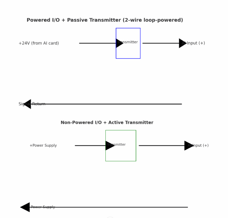
4. Recommended Wiring Diagrams
A. Powered I/O + Passive Transmitter (2-wire loop-powered)
sql
+24V (from AI card) -----> + Transmitter -||
Signal Return<----------- - AI Input
B. Non-Powered I/O + Active Transmitter
diff
+ Transmitter -----> + External Power
                      |
                      |
- Transmitter --------> AI Input (Signal)
📌 For 4-20mA loops, ensure proper current flow direction and that total loop resistance is within allowable range.
5. Summary
Transmitter Type
DCS Card Mode
Jumper Setting
Power Source
Typical Use Case
Passive (2-wire)
Powered
JPx: 1–2
From DCS card
Most field sensors
Active (3/4-wire)
Non-Powered
JPx: 2–3
Internal/External
Advanced transmitters with diagnostics
Understanding this mapping is essential for proper installation and commissioning of instrumentation systems. Misunderstanding jumper settings may lead to field malfunctions or commissioning delays.